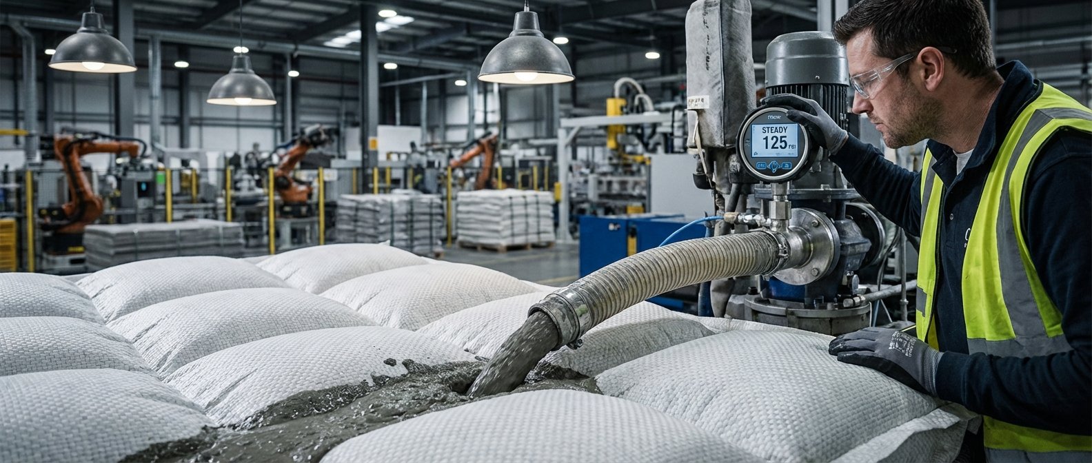
Most technical documents covering erosion control focus entirely on the architectural parameters of the fabric formwork. Project managers and site foremen know the real battle happens during the execution phase. A flawless specification sheet means nothing if the system suffers a massive blowout during the injection process.
After spending 10+ years optimizing engineered concrete mattresses and troubleshooting real field scenarios with w/c ratios hovering strictly around 0.45, it becomes obvious that execution dictates long-term stability. The difference between a resilient channel lining and a catastrophic field failure almost always circles back to how the fine aggregate mixture interacts with the fabric under active pump pressure.
Mastering a filter point concrete mattress pumping guide requires shifting your focus away from standard civil pouring techniques. Pumping a dual-layer woven fabric involves managing dynamic internal pressure, precise fluid mechanics, and unique geotextile tension limits.
The Anatomy of a Perfect Fill

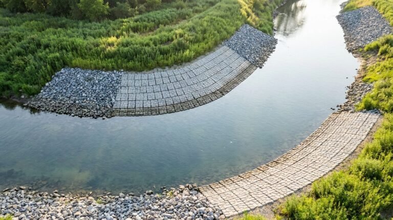
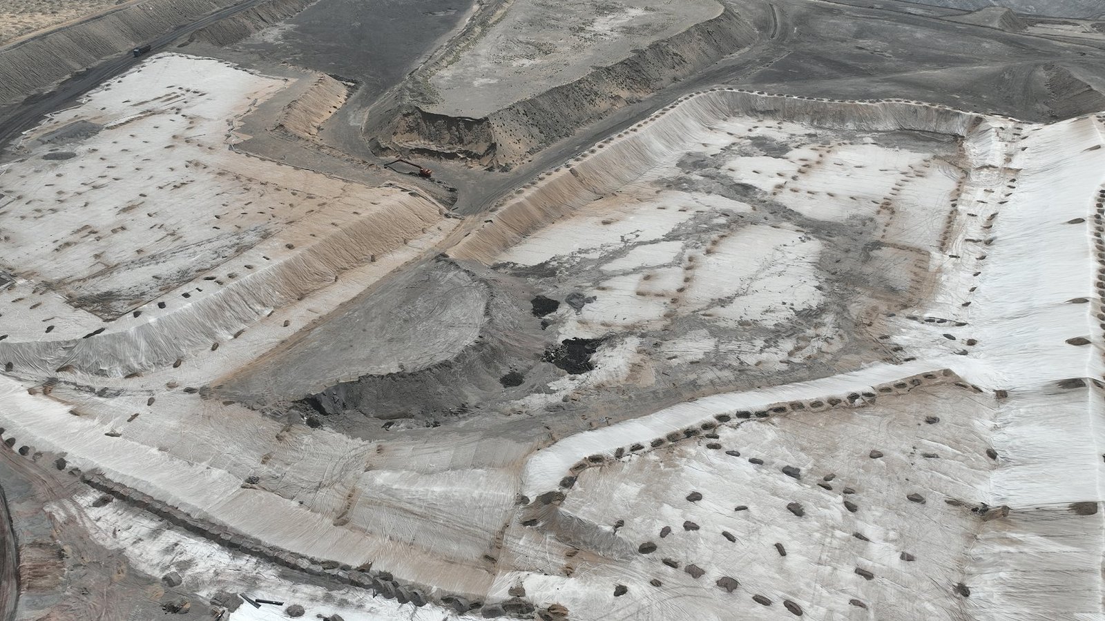
Understanding the structural constraints of the formwork is your primary step before ever firing up the line. This specific mattress design interlocks a non-woven geotextile backing with integrated weep zones that allow for critical groundwater relief.
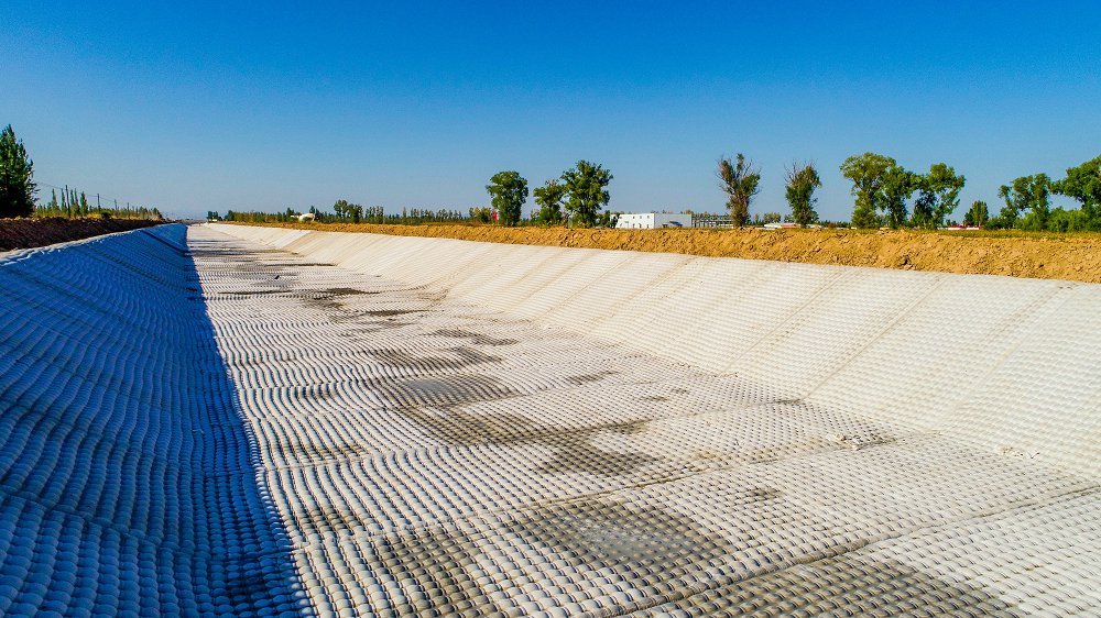
A standard installation requires filling these interconnected pillows to precise thicknesses, usually ranging from 100mm up to 300mm depending on the hydraulic shear models. The woven structure limits expansion, forcing the kinetic energy of the grout to travel laterally through the internal tubular network. Operators must balance the inflow rate against the fabric’s natural resistance to stretch.
Pushing material too fast forces the internal channels to choke. The aggregate bridges across narrow pathways, starving the distant panels of material while creating dangerous localized pressure spikes right at the injection nozzle.
Fine Aggregate Concrete Mix Design Tolerances
Standard ready-mix designs fail immediately inside fabric formworks. You cannot rely on conventional large coarse aggregates because they will instantly block the internal baffle structures of the mattress.
Your engineered mix must utilize a fine aggregate grading where the maximum particle size does not exceed 9.5mm. Creating a pumpable, flowable micro-concrete demands strictly controlled water-to-cement ratios, typically locked between 0.45 and 0.48. Going above this ratio invites excessive bleed water, which severely compromises the target concrete grade of C30/C35. Dropping below this ratio turns the mix too stiff to navigate the woven labyrinth.
Targeting a slump flow of 200mm is generally the sweet spot for these applications. High-range water reducers are non-negotiable here. They provide the necessary flowability without sacrificing the ultimate compressive strength required to resist anticipated scour velocities.
Dialing in Grout Pump Pressure Settings

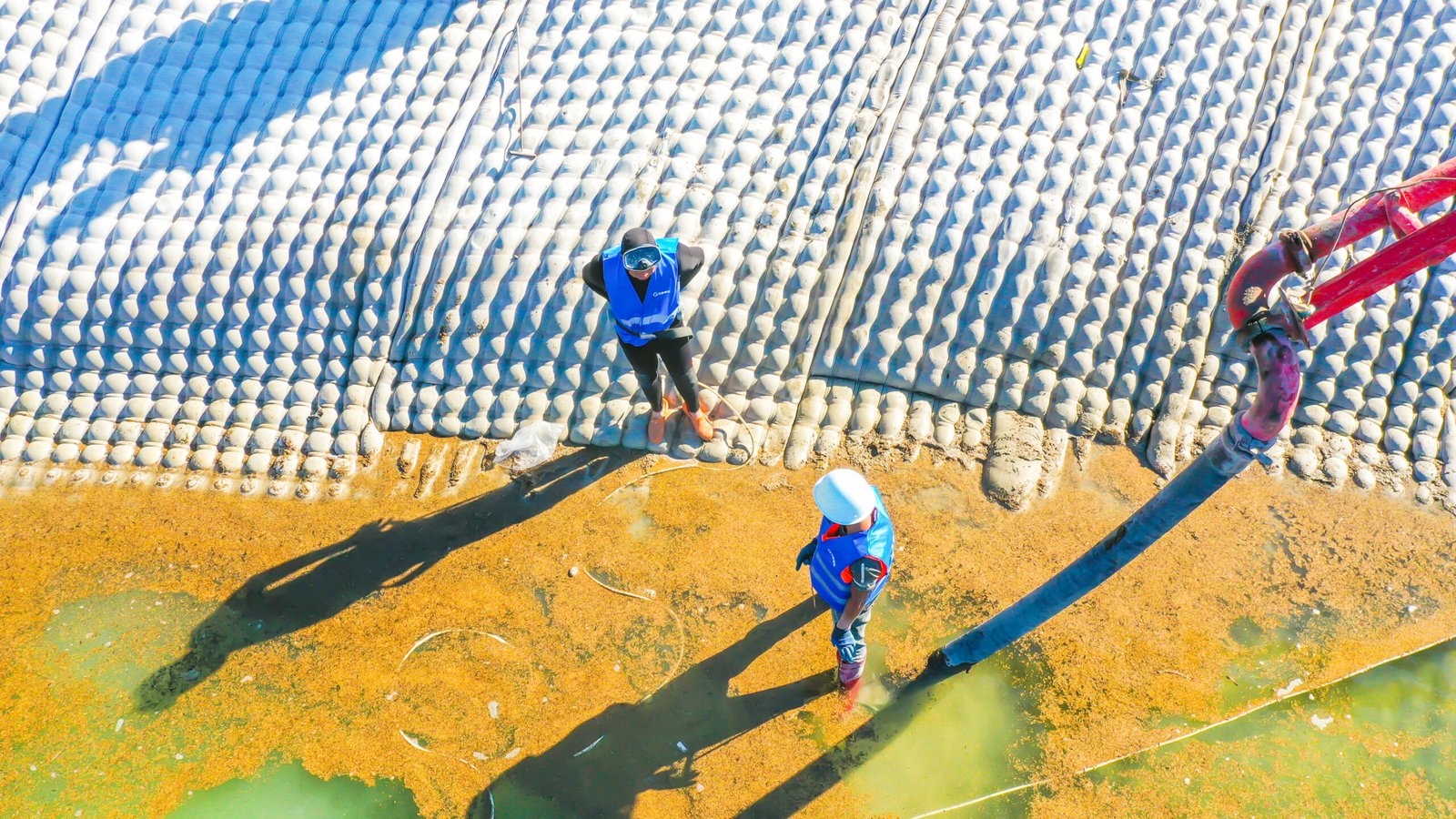
Field mechanics often treat grout pumps like blunt instruments. Blasting a high-volume flow straight into an empty geotextile form is a guaranteed way to blow a seam wide open.
You need to dial it in gradually. Initiating the fill requires a low, controlled pressure setting to allow the fabric time to expand uniformly and seat itself against the subgrade. Most experienced operators recommend keeping the line pressure under 15 psi at the initial injection collar. Once the internal pathways establish their structural shape, you can marginally increase the flow rate to match the continuous volume demands of the spreading radius.
Spikes in line pressure usually indicate an aggregate bridge blocking a channel. Forcing the pump to push through a blockage transfers sudden, immense kinetic force directly onto the woven transverse threads. Backing off the throttle and physically walking the mattress to manually manipulate the blockage is the only safe remediation protocol.
Filling Fabric Formwork Underwater
Submerged applications introduce entirely new variables to the handling sequence. Water resource engineers specifying these systems for active channels must account for buoyancy, flow velocity, and material displacement limits.
When you start injecting the fine aggregate mix underwater, the material must effectively displace the water currently occupying the internal fabric voids. Operating from the lowest elevation point and slowly working upward forces the trapped water out through the upper permeation zones. Your nozzle insertion points must be meticulously planned to ensure progressive upward filling without trapping dead pockets of water.
The integrated filter points hold a specific permeability coefficient (often around 1.5 x 10^-2 cm/s) designed to release trapped fluids safely. Rushing the subaqueous fill overwhelms this woven relief system. The resulting trapped water creates hollow voids inside the cured mattress, severely reducing its unit weight and rendering it vulnerable to uplift forces.
Managing Slope Gradients During Injection

Gravity can be a highly destructive force when pumping flowable grout down steep geometric profiles. Injecting material from the crest of an embankment slope allows the mix to rush downward, creating dangerous hydraulic head pressures at the toe of the formwork.
Contractors must employ a bottom-up pumping sequence. Starting at the toe trench anchors the entire continuous sheet against the subgrade. As the pillows inflate sequentially up the slope, they naturally lock into the soil profile. This upward progression maintains a controlled, packed density within the fabric channels while completely eliminating empty void risks.
Controlling the slump is vital when navigating steep gradients. If the flowability is too high, the material slumps downward inside the unhardened pillows, causing excessive bulging at the bottom and dangerously thin cross-sections near the crest.
Filter Point Spacing and Groundwater Relief

The woven nodal points are the defining architectural feature of this system. They act as dynamic pressure release valves not just during the service life of the lining, but actively during the injection process.
Standard mattress forms utilize spacing centers between 150mm and 300mm. When pumping the grout, you will actively see bleed water escaping through these specific designated mesh zones. This is intentional and necessary. The expulsion of excess water drops the internal water-cement ratio slightly within the fabric, accelerating the initial set time and increasing the localized density of the concrete.
Blocking these drainage zones with improper aggregate choices traps the active groundwater pressure beneath the impermeable sections. Allowing the filter areas to function undisturbed guarantees adequate uplift pressure resistance once the system is fully cured.
Overcoming Common Installation Obstacles
Weather conditions radically alter how your fine aggregate behaves inside the hoses and the formwork. High ambient temperatures accelerate hydration, causing the slump to drop rapidly inside the delivery line.
Cold joints are a common risk during complex, multi-day installs. If a pump fails or a ready-mix truck is delayed, the active leading edge of the wet concrete inside the fabric begins to handle. Pumping fresh material against a rigid edge creates a structural weak point. Operators inject water or retarders into the unfinished edge to keep the mix alive while resolving surface-level logistical delays.
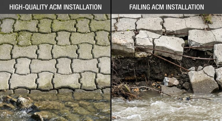
Uneven pillow thickness presents another frequent headache. This usually stems from a poorly prepared subgrade. The fabric forms exactly to the contours of the earth beneath it. Taking shortcuts during the final grade preparation guarantees an erratic final concrete profile that will fail to meet standard scour velocity resistance metrics.
Sourcing Robust Material for High-Pressure Fills
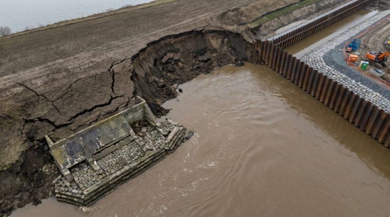
Even perfect pump handling cannot save a project burdened by substandard woven textiles. When evaluating manufacturing causes of river bank failure, fabric ruptures consistently rank as a primary culprit.
Protecting your margins in the field requires specifying materials designed explicitly for high-stress injection environments. Manufacturers like HydroBase approach the weaving process recognizing that field conditions rarely match laboratory ideals. They engineer their transverse threads to deliver a seam peel strength exceeding 50 kN/m.
This specific tensile threshold forgives minor pressure mistakes made by pump operators. When a sudden line surge occurs, low-grade fabrics split at the seams, spilling expensive grout directly into the waterway. Utilizing industrial-grade formwork components ensures those kinetic spikes are safely absorbed by the geotextile matrix rather than transferring into catastrophic mechanical failure.
Site Readiness Pumping Checklist
Establishing a standardized verification process saves endless frustration on pour day. Field operations managers need a rigid protocol that verifies both the material and mechanical readiness before authoring the first batch drop.
| Verification Stage | Inspection Criteria | Target Metric / Requirement |
|---|---|---|
| Material Verification | Max Aggregate Size Check | Strictly ≤ 9.5mm (3/8″) |
| Mix Consistency | Slump Measurement | 200mm to 220mm |
| Mechanical Setup | Pump Line Pressure limit | Initial 15 psi start |
| Placement Sequence | Trajectory Strategy | Bottom-to-Top strict routing |
| Anchor Integrity | Toe Trench Placement | Minimum 600mm bury depth |
| Flow Operation | Continuous Feed Protocol | < 15 minute gap between trucks |
Utilizing a visual checklist creates accountability across entirely different execution teams. The ready-mix supplier, the pump contractor, and the fabric installation crew must all align to these operational standards to execute a seamless operation. Minor deviations in the aggregate size or pump velocity will invalidate the entire structural intent of the engineering design.
Manufacturing Precision and Field Efficiency

Consistent field results demand flawless factory precision. Relying on inconsistent weaving patterns introduces unpredictable expansion rates during the fill process.
Top-tier production facilities utilize automated loom technologies to maintain perfect geometric tension across massive textile blocks. Advanced systems like the filter point concrete mattress engineered by HydroBase leverage precision manufacturing to guarantee exact spacing tolerances. When the spacing between the groundwater relief points is mathematically perfect, the grout flows through the internal chambers with predictable hydraulic resistance.
This predictability allows field engineers to calculate their required aggregate volumes down to the decimal. Taking the guesswork out of the internal volume parameters stops costly over-ordering and eliminates the risk of running dry mid-pour.
Frequently Asked Questions
Q: What is the optimal slump for filter point concrete mattress pumping?
The ideal slump flow sits squarely between 200mm and 220mm. Achieving this high workability without exceeding a 0.48 water-cement ratio requires the use of specialized high-range water reducers. This highly fluid state allows the fine aggregate mix to navigate the internal woven baffles without bridging or blocking.
Q: How do you calculate the exact grout volume needed per square meter?
You calculate internal volume by multiplying the precise square meter coverage by the designated average thickness of the mattress style (e.g., 150mm standard thickness). Manufacturers advise adding a 10% waste factor to accommodate minor subgrade irregularities and line priming requirements, ensuring you do not run short on material.
Q: What causes seam rupture during the filling process?
Seam ruptures happen when high concrete flow rates meet internal aggregate blockages. The pump builds localized kinetic pressure that exceeds the fabric’s seam peel strength limits. Avoiding standard coarse aggregates and maintaining a slow, deliberate initial flow rate prevents sudden impact stress on the woven joints.
Q: What is the difference between articulated block systems and filter point fabric forms?
Articulated systems arrive at the site as pre-cast concrete blocks connected by cables, while filter point systems arrive as empty fabric rolls that are pumped with fluid grout on-site. Fabric forms adapt perfectly to highly irregular ground contours, whereas pre-cast blocks require much flatter planar subgrade conditions.
Q: How do lead times impact custom fabric formwork project schedules?
Standard custom manufacturing and delivery cycles for large-scale fabric orders normally span 4 to 6 weeks. However, dedicated B2B suppliers like HydroBase often maintain extensive raw inventory capable of expediting tailored dimension requests, ensuring contractors can meet aggressive deployment deadlines without sacrificing strict quality metrics.
Maximizing Hydraulic Protection Through Better Execution
Securing long-term bank stability relies significantly on what happens during the volatile pumping phase. A perfectly specified vegetated concrete mattress or standard erosion lining only realizes its mathematical potential if the internal concrete matrix remains intact, uniform, and dense.
Prioritizing your aggregate selection, respecting the slump limits, and deploying a strict bottom-up subaqueous execution strategy eliminates the overwhelming majority of field failures. Operators who manage pump sequence pressure with patience avoid ruptured seams and inconsistent pillow volumes. Aligning excellent site preparation with industrial-strength woven materials ensures your completed system effortlessly deflects high scour velocities for decades.
Engineers heavily invested in mitigating active hydraulic erosion need access to actionable, field-tested installation parameters. Download the definitive filter point concrete mattress specification sheet to align your next execution sequence with strict global tolerances. Ensure your field teams have the specific mix design guidelines necessary to deliver a flawless, blowout-free installation.