Articulated Concrete Mattress Installation: Step-by-Step Guide for Site Engineers and Contractors
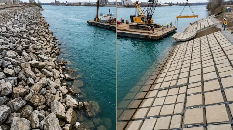
**Quick Answer:** The concrete mattress installation method follows six key stages: site preparation and subgrade grading → geotextile filter layer placement → ACM panel positioning via crane or float-and-sink → cable termination and tensioning → anchor trench excavation and backfill → post-installation bathymetric or visual survey. Underwater placement requires a spreader bar frame and diver or ROV confirmation at each panel joint.
Getting ACM installation right the first time matters — not just for project compliance, but because remedial underwater work costs three to five times more than doing it correctly on the first pass. With 18 years of manufacturing and field advisory experience at HydroBase, I’ve seen projects succeed and fail based on how well the installation team understood the method before the first panel hit the water.
This guide gives site engineers, construction superintendents, and contractor QA teams a complete concrete mattress installation method statement they can adapt directly into their project QA plan.
Table of Contents
- Pre-Installation: Site Preparation
- Step 1 — Geotextile Filter Placement
- Step 2 — Panel Delivery and Positioning
- Step 3 — Underwater Placement Method
- Step 4 — Cable Termination
- Step 5 — Anchor Trench
- Step 6 — Post-Installation Survey
- Common Installation Errors
- Frequently Asked Questions
Pre-Installation: Site Preparation
Before a single panel leaves the staging area, the subgrade must be within specification. For articulated concrete mattress installations, the subgrade tolerance is typically ±75mm from the design profile — tighter tolerances apply for pipeline spanning applications. Any irregular depressions deeper than 150mm need to be filled and compacted before the geotextile goes down.
**Subgrade grading checklist before ACM placement:**
- Remove all sharp objects, debris, and vegetation root masses greater than 50mm diameter
- Compact fill material to minimum 95% standard Proctor density (ASTM D698)
- Verify slope gradient matches design — typical ACM applications run from 1:1.5 to 1:3 (V:H)
- Confirm drainage path so groundwater doesn’t migrate under the geotextile layer during placement
- Mark out panel overlap zones (minimum 300mm overlap at adjacent panel edges)
- Establish survey control points at 10m intervals along the protection zone
Underwater site preparation deserves particular attention. Side-scan sonar or multibeam echo sounder surveys should be completed no more than 48 hours before placement to confirm the bed profile hasn’t shifted. In active channels with mean velocities exceeding 1.5 m/s, this window shrinks to 24 hours.
Don’t skip the equipment pre-mobilisation check either. Confirm crane lift capacity against the heaviest panel weight in the delivery batch — standard ACM panels range from 50 kg/m² to 400 kg/m² depending on block geometry (300×200×100mm up to 600×400×200mm), and a 6m × 3m panel at 200 kg/m² weighs 3,600 kg before rigging hardware.
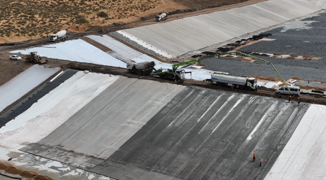
Step 1 — Geotextile Filter Placement

The geotextile filter layer is the most underestimated component in the concrete mattress laying method. Get it wrong here and you’ll have piping failure regardless of how well the ACM panels sit on top.
**Geotextile selection parameters:**
- Apparent Opening Size (AOS / O₉₅): must be ≤ D₈₅ of the subgrade material (filter compatibility criterion per FHWA HEC-11)
- Permittivity: minimum 0.1 sec⁻¹ for most revetment applications; 0.5 sec⁻¹ or higher for tidal or fluctuating water table zones
- Grab tensile strength: minimum 900N (ASTM D4632) for handling under ACM panel weight
- UV resistance: Class A rating if the filter edge will be exposed at the crest
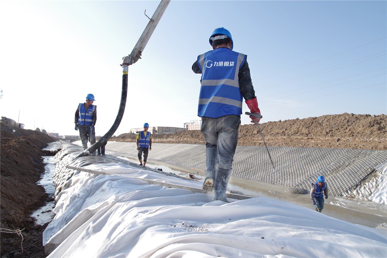
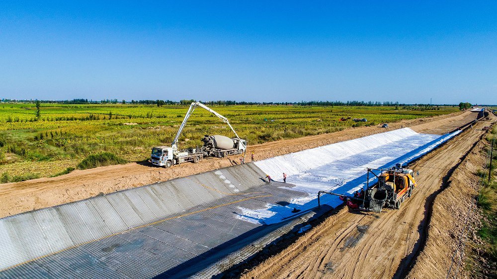
**Placement sequence:**
Roll the geotextile from the toe upward on slopes — never from the crest down. Rolling downslope causes the fabric to bunch under the weight of the roll, creating wrinkles that trap sediment and reduce filter efficiency. Overlap adjacent rolls by a minimum of 600mm (or 1,000mm in areas with flow velocity exceeding 2.5 m/s).
Secure the geotextile with U-staples at 1.5m centres along the overlap seam and at 3m centres across the panel face. In underwater applications, the geotextile is often pre-attached to the underside of the ACM panel using cable ties through factory-installed attachment points — this eliminates the separate fabric placement dive entirely and reduces bottom time significantly.
Inspect the fabric after placement and before ACM panel deployment. Look for tears larger than 25mm, exposed staple heads that have pulled through, and any areas where the fabric has been stretched tight over a subgrade high point — this creates a stress concentration that will tear when the ACM weight loads it.
For canal lining projects, the canal lining with articulated concrete mattress design guide covers filter compatibility calculations in detail, including worked examples for cohesive and granular subgrades.
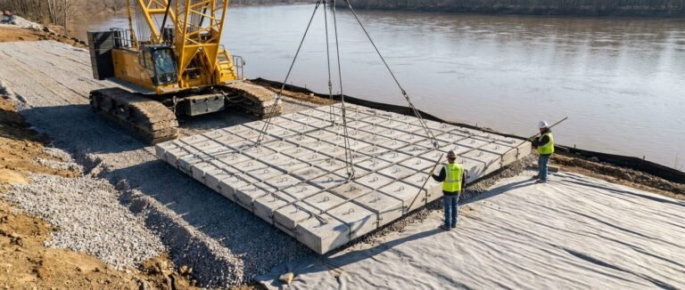
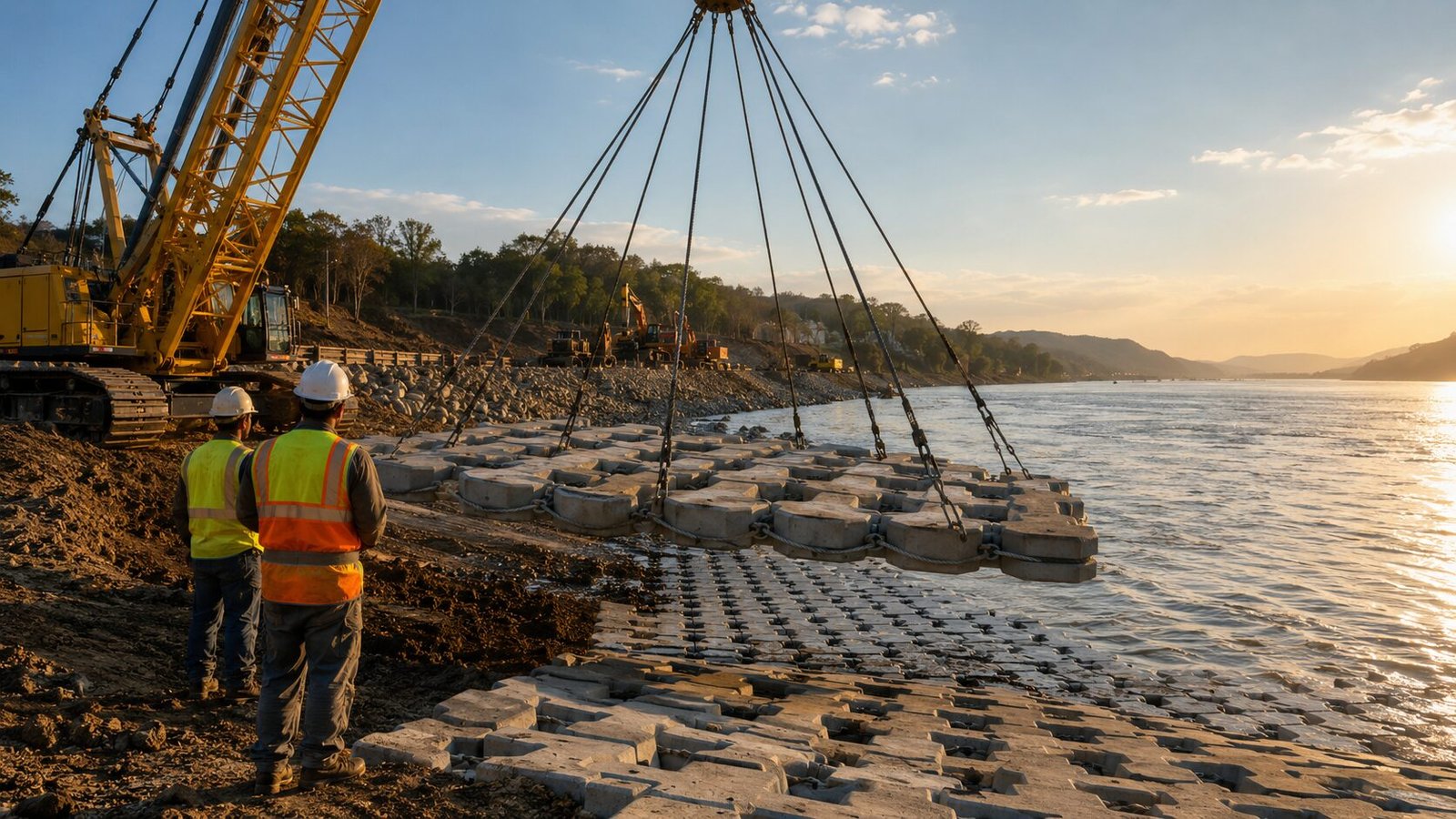
Step 2 — Panel Delivery and Positioning
Panel staging and sequencing on site directly affects installation speed and panel integrity. Panels should be offloaded to a hardstand area within crane reach of the placement zone — dragging ACM panels across ground damages the cable system at the connector points.
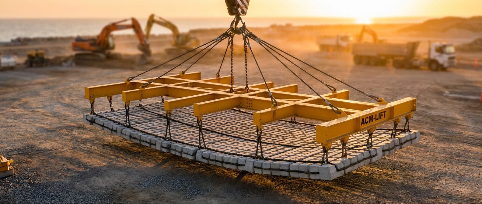
**Rigging configuration:**
Use a four-point lifting frame (spreader bar frame) with adjustable leg lengths. The spreader bar must distribute the load so no single lift point carries more than 35% of the total panel weight — uneven loading creates cable tension that can snap individual strand wires before the panel even reaches the water.
Attach shackles only to factory-installed lifting eyes or designated cable loop terminations. Never rig through the structural cables themselves. Confirm shackle SWL (Safe Working Load) is at minimum 2× the calculated point load with a Dynamic Amplification Factor of 1.3 applied for water entry.
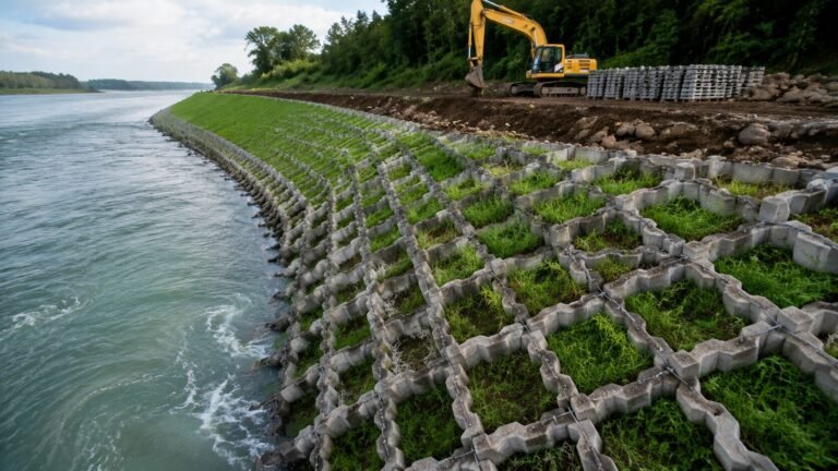
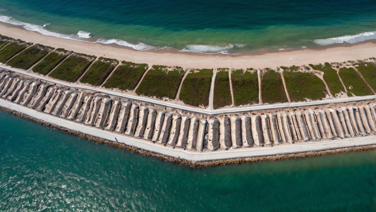
Panel sequencing follows a toe-first rule on slopes: place the lowest panel first and work up the slope, allowing each successive panel to lap over the one below. This creates a shingle-effect overlap that resists uplift from hydrodynamic forces. On flat bed applications (bridge pier scour, pipeline protection), place from the downstream edge and work upstream so panels are lapped against the prevailing current direction.
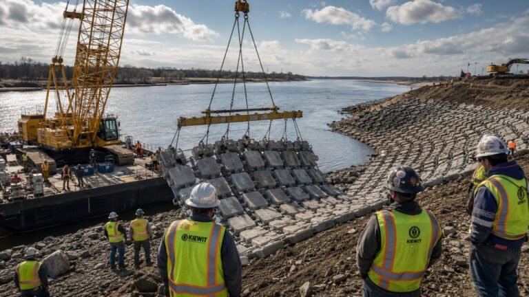
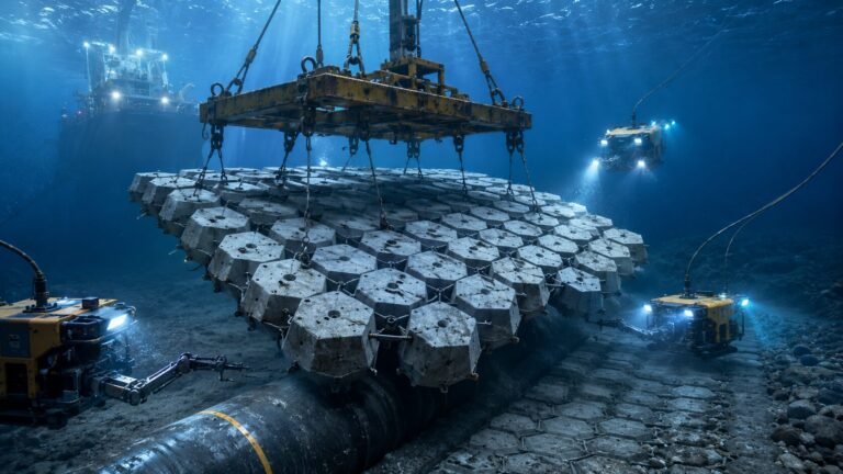
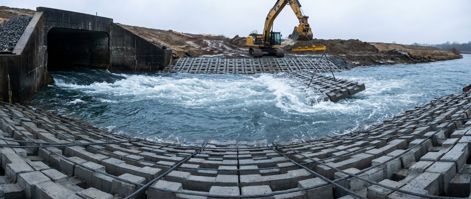
Step 3 — Underwater Placement Method
ACM underwater installation is where most errors happen — and most go undetected until a post-installation survey reveals panel gaps or overlaps outside tolerance.
**Float-and-sink method (for panels up to approximately 3.0 m/s current velocity):**
The panel is suspended horizontally from a crane barge or land-based crane and lowered until it just contacts the water surface. At that point, lower speed is reduced to approximately 0.3 m/s to allow the panel to settle through the water column without oscillating. A diver or ROV monitors the panel’s descent from a downstream position and calls for crane position corrections via surface radio.
Critical parameters for underwater placement:
- Maximum lateral drift tolerance during lowering: ±200mm from design centerline
- Maximum placement depth without diver confirmation: 6m (below this, ROV guidance is required)
- Minimum slack in crane wire at touchdown: 150mm (prevents panel bouncing on seabed impact)
- Current velocity limit for float-and-sink: 1.5 m/s at the placement elevation
**Crane barge method (for deeper water and higher current velocities):**
For ACM underwater installation in depths exceeding 8m or currents above 1.5 m/s, a crane barge with dynamic positioning (DP1 minimum) is standard. The barge holds station while the panel is lowered on a guided frame with vertical guide wires pre-installed on the seabed. Panel position is confirmed by acoustic positioning transponders attached to the lifting frame corners.
After each panel touchdown, the diver confirms panel-to-panel overlap (minimum 300mm at all edges) before the crane releases the rigging. Any panel that has landed with less than 150mm overlap must be lifted and repositioned — do not attempt to slide panels into position on the seabed.
Step 4 — Cable Termination
Cable termination is the structural connection point between adjacent ACM panels. A failed termination doesn’t just disconnect two panels — it can unravel cable routing through an entire panel row.
**Standard cable termination procedure:**
ACM systems use either polypropylene rope or stainless steel cable (SS316 for marine environments, SS304 for freshwater). At panel edges, the cable is terminated using one of three methods:
- **Loop-and-pin termination**: The cable loop is passed through the factory-installed connector block and secured with a stainless steel pin and split cotter. Minimum pin diameter: 12mm for panels up to 250 kg/m².
- **Swaged ferrule termination**: Steel cable is swaged into a ferrule at the factory. Field connection uses a shackle or clevis pin. Inspect swage integrity before every panel — a cracked swage is a panel failure waiting to happen.
- **Rope splice termination**: Used in rope-tied ACM systems. Minimum splice length = 300mm. Check splice for crown separation before lowering.
Cable tension after termination should be verified by hand-feel for rope systems (no visible sag across the panel span) or by torque wrench for bolted connector blocks (typically 45–65 N·m depending on block size).
For a detailed comparison of slab versus block panel configurations and their respective cable systems, the guide on articulated concrete slab mattress specifications and applications covers connector geometry differences clearly.
Step 5 — Anchor Trench
The anchor trench locks the upslope and toe edges of the ACM installation against uplift and creep. Inadequate anchor trenches are responsible for a disproportionate number of ACM revetment failures — the panels themselves are intact, but the whole system peels back from the edge.
**Anchor trench minimum dimensions (standard revetment applications):**
| Location | Trench Width | Trench Depth | Backfill Compaction |
|---|---|---|---|
| Crest (top of slope) | 600mm | 600mm | 95% Proctor |
| Toe (base of slope, dry) | 500mm | 500mm | 95% Proctor |
| Toe (base of slope, submerged) | 600mm | 800mm | Granular, no compaction |
| Midslope (where panels join on slopes >1:1.5) | 450mm | 450mm | 95% Proctor |
For submerged toe trenches, use clean granular backfill (D₅₀ > 20mm) to allow drainage without piping — compacting saturated fine material in a submerged trench achieves nothing and creates a false sense of security.
Turn the geotextile filter into the trench before placing the ACM panel edge. The geotextile should extend at least 300mm past the panel termination edge inside the trench. Backfill the trench in 200mm compacted lifts, confirming each lift before proceeding.
Step 6 — Post-Installation Survey
No ACM installation is complete without a documented post-installation survey. This is your QC sign-off and your baseline for any future monitoring.
**Survey methods by water depth:**
- **Dry/exposed applications**: Visual walk-over survey with photo documentation at 5m intervals. Confirm panel overlap, cable condition, anchor trench backfill, and geotextile edge exposure.
- **Shallow water (0–3m)**: Wading survey with probe rod. Check panel seating at minimum 3 points per panel. Compare probe measurements to design bed level.
- **Deep water (>3m)**: Multibeam echo sounder survey or ROV video. Minimum horizontal resolution: 0.25m × 0.25m. Compare post-installation bathymetric surface to design surface — any deviation greater than ±100mm warrants diver investigation.
Document every survey with GPS coordinates, timestamps, and photographic evidence. Any panel gap greater than 50mm requires remediation before the installation is accepted.
For scour-critical applications — bridge piers, abutments, culvert outlets — a follow-up survey at 30 days post-installation is standard practice, since initial scour events often occur in the first high-flow season.
Common Installation Errors
After reviewing dozens of ACM installation records, the same errors appear repeatedly:
**1. Geotextile placed over wet, soft subgrade without adequate drainage**
Water trapped beneath the geotextile will migrate toward the toe under ACM weight, carrying fines and creating settlement voids. Pre-drainage is not optional in saturated conditions.
**2. Panels placed crest-to-toe instead of toe-to-crest**
This creates downstream-facing overlaps that current will get under. Always start at the toe.
**3. Cable termination skipped at the last panel in a row**
It happens on every long project at least once — the crew is tired, it’s the last panel, the termination gets left loose. A loose termination lets the cable unthread from all adjacent blocks under flow.
**4. Anchor trench backfilled with excavated fine material**
Silty excavated material compacts poorly when wet and washes out under seepage. Use specified granular backfill.
**5. No panel-by-panel survey record**
When a panel gap is discovered six months later, there’s no way to determine whether it was installed that way or shifted. Document every panel position before moving to the next.
For context on how installation quality connects to long-term scour performance, the article on how articulated concrete mattresses protect riverbeds from scour is worth reading alongside this guide.
QC Checklist: ACM Installation Method Statement
Use this checklist as a field QA document. Each line item should be signed off by the site engineer before progressing to the next stage.
| Stage | QC Item | Pass Criteria | Sign-Off |
|---|---|---|---|
| Site Prep | Subgrade graded to tolerance | ±75mm from design profile | |
| Site Prep | Debris and vegetation removed | No items >50mm remaining | |
| Geotextile | Roll direction confirmed | Toe-upward on slopes | |
| Geotextile | Overlap width measured | ≥600mm (≥1,000mm in high-flow zones) | |
| Geotextile | Staple spacing confirmed | 1.5m on overlaps, 3.0m on field | |
| Panel Rigging | Spreader bar lift points checked | No single point >35% total panel weight | |
| Panel Rigging | Shackle SWL verified | ≥2× point load with DAF 1.3 | |
| Panel Sequence | Toe-first placement confirmed | Each panel laps over panel below | |
| Underwater | Diver/ROV confirmation obtained | Panel-to-panel overlap ≥300mm | |
| Underwater | Current velocity at placement depth checked | <1.5 m/s for float-and-sink | |
| Cable Termination | Pin/swage/splice integrity checked | No cracks, gaps, or separation | |
| Cable Termination | Cable tension verified | No visible sag; torque per spec | |
| Anchor Trench | Dimensions confirmed before backfill | Per design minimum dimensions | |
| Anchor Trench | Backfill material verified | Granular per specification | |
| Survey | Post-installation survey completed | All gaps <50mm; panels seated to design level |
Frequently Asked Questions
Q: What is the maximum flow velocity an articulated concrete mattress can handle?
Standard ACM systems are velocity-rated up to 6.0 m/s for heavy block configurations (600×400×200mm, approximately 400 kg/m²). Lighter open-pattern systems (300×200×100mm) are typically rated to 3.5–4.0 m/s. Velocity rating depends on block weight, cable system, and whether the mattress is anchored at toe and crest — an unanchored edge reduces the effective rating by approximately 20–30%.
Q: How long does it take to install one ACM panel underwater?
A trained two-diver crew with crane barge support typically achieves 3–5 panels per hour in water depths up to 8m and currents below 1.0 m/s. At greater depths or higher currents, production drops to 1–2 panels per hour due to extended positioning and confirmation time. Panel size, rigging configuration, and seabed irregularity all influence the rate.
Q: What is the difference between cable-tied and rope-tied ACM systems?
Cable-tied systems use stainless steel wire rope (SS316 for marine, SS304 for freshwater) with swaged or pin-locked terminations. They offer higher tensile strength and are preferred for high-velocity or marine applications. Rope-tied systems use polypropylene or polyester rope and are more flexible, easier to repair in the field, and typically lower cost. Rope systems are common in irrigation canal and river revetment applications where velocity ratings below 4.0 m/s are acceptable.
Q: What are typical lead times and minimum order quantities for ACM panels?
Lead times for standard ACM configurations typically run 3–6 weeks from order confirmation, depending on panel size and quantity. Manufacturers like HydroBase generally require minimum orders in the range of 200–500 m² for standard production runs, though sample quantities for testing and specification approval are usually available at lower MOQ. Confirm with your supplier whether the quote includes cable installation at the factory or field termination.
Download the ACM Installation Method Statement Template
Site teams that have reviewed this guide are often looking for a formatted method statement they can submit directly to a project engineer for QA approval. HydroBase’s articulated concrete mattress product page includes downloadable technical datasheets covering standard panel configurations (block sizes 300×200×100mm through 600×400×200mm), velocity rating tables, and cable specification options across the full weight range of 50–400 kg/m².
If your project involves non-standard slope angles, unusual flow regimes, or combined ACM and scour protection systems, the concrete mattress thickness design guide with worked examples walks through the HEC-23 sizing methodology with real design scenarios.
To request a project-specific technical datasheet or panel weight schedule aligned to your design velocity, reach out through the product page with your project flow parameters and installation depth — the team turns around technical responses within one business day.
Conclusion
A well-executed concrete mattress installation method is part engineering, part logistics, and part disciplined QC documentation. The six steps in this guide — subgrade preparation, geotextile placement, panel positioning, cable termination, anchor trench construction, and post-installation survey — form a complete method statement framework that holds up under project scrutiny.
Where most installations fall short isn’t in the major steps. It’s in the details: geotextile roll direction, anchor trench backfill material, cable termination on the last panel of a run, and the survey that confirms everything is where it’s supposed to be.
As ACM systems move into deeper water applications and higher-velocity environments, underwater placement methods and ROV confirmation protocols are becoming baseline expectations rather than premium options. Site engineers who understand the complete installation sequence — from subgrade tolerances through post-installation bathymetry — are the ones who deliver projects that perform for the 25–50 year design life these systems are specified for.
Need a concrete mattress solution for your project?
HydroBase provides end-to-end concrete mattress engineering & installation services — from hydraulic design and factory-direct ACM supply to on-site supervision and post-project inspection. Trusted by civil engineers in 50+ countries.