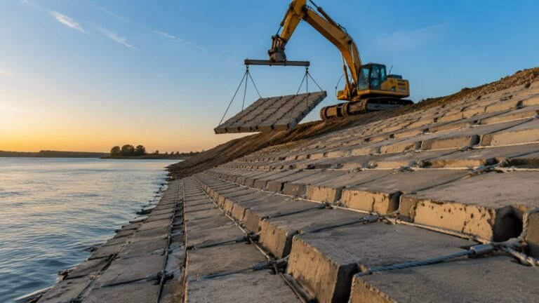
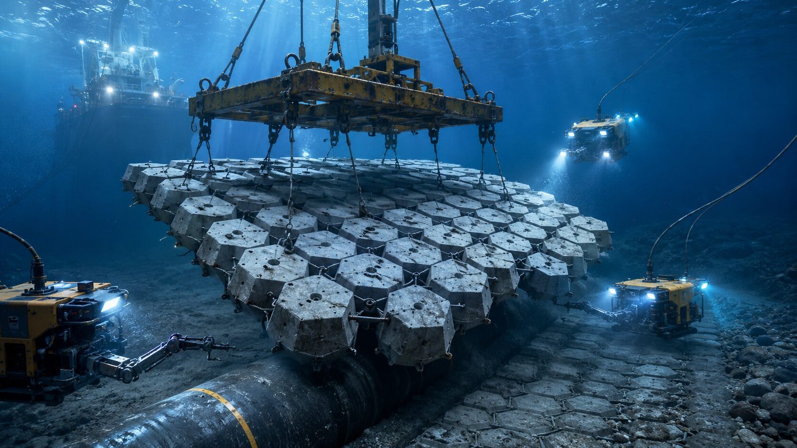
ACM for Offshore Pipeline Stabilization: Design Requirements & Installation
Quick Answer: Offshore concrete mattress pipeline stabilization provides additional on-bottom weight to resist hydrodynamic uplift forces from waves and currents. Design follows DNV-RP-F109 methodology. Standard configuration uses 200–300 mm thick flat or semi-open blocks with HDPE-sheathed cable systems, deployed by ROV-guided barge crane or direct submersion from a lay vessel.
Subsea pipelines face a unique engineering challenge that onshore infrastructure never encounters: they must resist continuous hydrodynamic forces in an environment where inspection is expensive, maintenance is dangerous, and failure consequences are severe. With 18 years of experience manufacturing articulated concrete mattress systems for offshore projects across Southeast Asia and the Middle East, I’ve seen firsthand how the wrong stabilization approach creates costly remediation campaigns — and how the right one performs without issue for decades. This guide covers the engineering fundamentals offshore pipeline engineers need when evaluating offshore concrete mattress pipeline solutions.
Table of Contents
- Why Pipelines Need On-Bottom Stabilisation
- DNV-RP-F109 Design Approach
- ACM vs Concrete Coating vs Grout Bags
- ACM Specification for Offshore: Key Differences
- ROV Deployment Methods
- Case Reference: Pipeline Crossing Protection
- Frequently Asked Questions
Why Pipelines Need On-Bottom Stabilisation
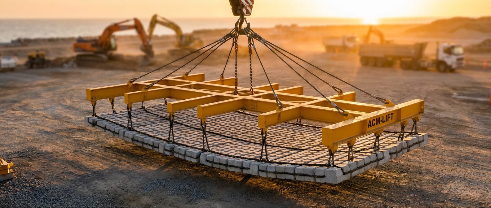
A subsea pipeline resting on the seabed isn’t automatically stable. Even steel pipe with standard concrete weight coating can become hydrodynamically buoyant under certain wave and current conditions — particularly in shallow water where oscillatory wave action dominates and in areas of strong tidal flow.
The fundamental problem is buoyancy versus submerged weight. A 16-inch gas pipeline with 40 mm concrete weight coating at 50 m water depth might have a submerged weight of 1.8 kN/m. That sounds substantial, but under storm conditions with a Hs of 4.5 m and a peak current of 0.8 m/s, the hydrodynamic lift force can easily exceed 2.5 kN/m — and that’s before accounting for drag forces in the horizontal plane.
Shallow-water crossings amplify this problem dramatically. River mouths, tidal inlets, and nearshore sections from 5 m to 30 m water depth sit right in the zone where wave-induced velocities are strongest relative to water depth. Free-spanning — where the pipe lifts off the seabed and oscillates — leads to fatigue damage at girth welds, which is one of the leading causes of offshore pipeline failures.
Three primary mechanisms require stabilization engineering:
- Hydrodynamic uplift from wave-induced oscillatory flow and steady current drag
- Lateral walking over time, driven by cyclic loading during pressure and temperature cycles
- Seabed scour that creates unsupported spans, increasing stress concentrations
On-bottom stabilisation strategies generally fall into three categories: increasing submerged weight (concrete coating, concrete mattress, grout bag), mechanical anchoring (rock anchors, soil anchors), or seabed modification (rock dumping, trenching and backfill). Each approach suits different water depths, seabed conditions, and operational timelines.
For pipeline sections that are accessible post-installation — or where trenching isn’t viable — the offshore concrete mattress pipeline approach offers a specific combination of advantages: it adds significant distributed weight without requiring seabed penetration, it’s deployable by surface crane or ROV, and it allows future access to the pipeline for inspection.
DNV-RP-F109 Design Approach

DNV-RP-F109 (On-Bottom Stability Design of Submarine Pipelines) is the dominant international standard for this work and the framework that drives ACM sizing decisions on most offshore projects worldwide.
The recommended practice uses two primary design methods:
Simplified Method (Level 1): A conservative screening approach using non-dimensional stability parameters. The key stability parameter is:
Gs = (ws) / (0.5 × ρw × U²c × D)
Where ws = submerged weight per unit length (N/m), ρw = seawater density (typically 1,025 kg/m³), Uc = steady current velocity (m/s), and D = outer pipeline diameter including coating (m).
For absolute stability, Gs must exceed a threshold that depends on the Keulegan-Carpenter number (KC) — a dimensionless parameter combining wave-induced velocity amplitude, wave period, and pipe diameter.
Generalized Method (Level 2): A more refined force-based approach using FEM or response models, appropriate for detailed design on critical pipeline sections. This method allows partial displacement during design events, provided accumulated displacement stays within acceptable limits (typically 10–20 m lateral movement over the pipeline’s design life).
How ACM changes the calculation:
Adding an articulated concrete mattress to an under-stabilized pipeline section directly increases ws — the submerged weight per unit length. A 250 mm thick ACM with a block density of 2,400 kg/m³ and 35% open area adds approximately 3.8–4.2 kN/m² of downward force. Across a 12-inch (305 mm OD) pipeline, that translates to roughly 1.15–1.28 kN/m of additional stabilizing force per linear metre of mattress coverage.
The design process for ACM stabilization typically follows this sequence:
- Calculate the pipeline’s bare submerged weight from pipe wall and concrete coating specifications
- Determine the environmental loading from site-specific metocean data (wave scatter diagram, current rose)
- Apply DNV-RP-F109 Level 1 to identify sections failing the stability criterion
- Calculate the additional submerged weight needed to achieve Gs ≥ target value
- Select ACM thickness and block pattern to deliver that weight increment
- Check that the ACM itself won’t be displaced by hydrodynamic forces at the design velocity
A practical point that’s worth noting: DNV-RP-F109 doesn’t prescribe ACM as a solution — it specifies the stability criterion. How you meet that criterion is the engineer’s choice. ACM is particularly attractive when post-construction stabilization is needed (discovered during ROV survey), when trenching isn’t permitted (environmentally sensitive seabed), or when the pipeline needs to remain accessible.
ACM vs Concrete Coating vs Grout Bags
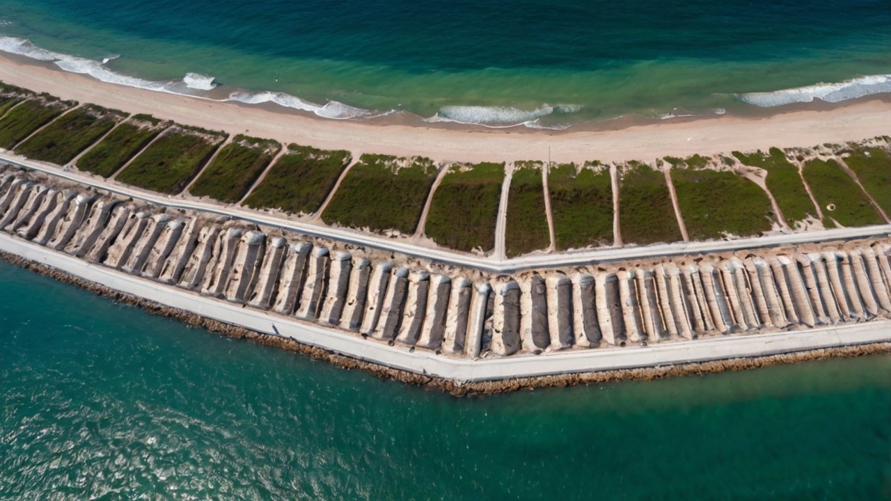
Choosing the right stabilization method comes down to project phase, water depth, seabed character, and whether the pipeline is already installed. Here’s an honest comparison:
| Parameter | Articulated Concrete Mattress | Concrete Weight Coating | Grout Bags |
|---|---|---|---|
| Application stage | Pre- or post-installation | Pre-installation only | Post-installation |
| Weight addition (kN/m²) | 2.5–6.0 | Fixed by design | 3.0–8.0 (variable) |
| Thickness range | 150–300 mm | 40–120 mm | 100–400 mm |
| Conformance to seabed | Excellent (articulated) | N/A (pipe coating) | Good (flexible bag) |
| Inspection access | Full (mattress removed or lifted) | Limited (integral coating) | Partial |
| Water depth capability | Proven to 200 m+ | Unlimited | Typically <100 m |
| Installation vessel | Crane barge, AHTS, DSV | Coating yard, lay vessel | Crane barge, ROV |
| Lead time to site | 8–14 weeks typical | Integrated in pipe schedule | 4–8 weeks |
| Unit cost (relative) | Medium | Low (integrated) | Medium–High |
| Scour protection | Yes (covers seabed approach) | No | Partial |
Concrete weight coating is the first choice when you’re still in pre-FEED or detailed design — it’s integrated into the pipe specification, costs less per unit weight added, and creates no offshore installation complexity. But it’s locked in at the coating yard. If your as-built stability calculation shows a problem after the pipe is laid, coating isn’t an option.
Grout bags are flexible and fast, but quality control is genuinely difficult. Bag fabric integrity, grout mix consistency, and underwater placement accuracy all affect the as-placed weight — and you rarely get the figure you calculated.
Articulated concrete mattress wins on two fronts: predictable weight (each block is a precast unit with a known density), and flexibility to conform to irregular seabed while still providing full coverage. For pipeline crossing protection — where the pipe crosses a scoured channel bottom — ACM is typically the most practical solution because it bridges the scour zone and pins the pipe to the natural seabed beyond it.
ACM Specification for Offshore: Key Differences
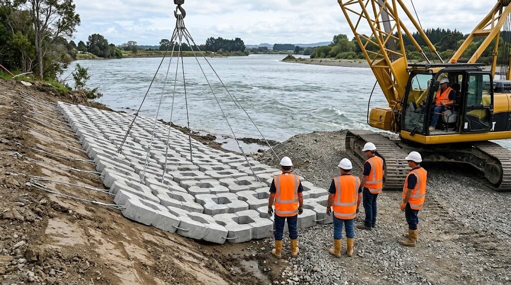
Offshore ACM specifications differ from river or coastal revetment designs in several important ways. Engineers sourcing for subsea projects need to pay attention to these parameters — they’re not always spelled out in generic product datasheets.
Concrete strength: Offshore ACM blocks should be specified at a minimum 45 MPa compressive strength (characteristic cube strength, 28-day). Subsea chloride exposure is severe — the combination of hydrostatic pressure, dissolved oxygen, and chloride ion concentration demands higher density concrete to limit permeability. Many river revetment mattresses are cast at 30–35 MPa; that’s not appropriate for long-term offshore service.
Cover to reinforcement: Where blocks contain embedded cable attachment points or lifting points, minimum concrete cover should be 50 mm in splash zone service and 40 mm in fully submerged service. Carbonation rates are lower underwater, but chloride attack is the governing mechanism.
Cable system: Standard ACM uses galvanized steel cable. Offshore specifications almost universally require HDPE-sheathed stainless steel (typically 316L grade) cable, minimum 8 mm diameter for mattresses heavier than 120 kg/m². HDPE sheathing prevents crevice corrosion at cable-block interfaces, which is the most common failure mode in marine ACM systems.
Block dimensions (offshore standard range):
- Length: 300–500 mm (shorter blocks = better conformance)
- Width: 200–350 mm
- Thickness: 200–300 mm (heavier than river applications)
- Open area: 20–40% (semi-open pattern preferred — reduces hydrodynamic uplift on mattress itself)
- Block weight: 12–48 kg per individual block
Mattress panel dimensions: Standard supply panels run 2.4 m × 6.0 m to 3.0 m × 12.0 m. Offshore crane capacities and vessel deck space constraints often drive panel sizing more than any engineering consideration — worth discussing with your installation contractor early.
Lifting system: Offshore ACMs require integrated spreader bar lifting frames rated and certified to the appropriate standard (typically DNV-ST-N001 or equivalent). The lifting frame weight should be included in crane capacity calculations — a 3 m × 9 m mattress panel at 250 mm thickness can weigh 14–18 tonnes in air, and crane reach at installation depth governs the maximum manageable panel size.
Geotextile interlayer: Unlike many river applications where the ACM is laid directly on prepared granular filter, offshore ACM typically incorporates an integral non-woven geotextile bonded to the underside. This maintains filter separation from the seabed sediment without requiring a separately placed filter layer — which is practically impossible to install underwater with any accuracy.
ROV Deployment Methods
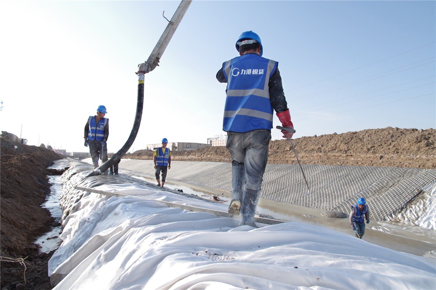
Deployment method selection depends on water depth, vessel capability, and pipeline diameter. Three approaches are used in practice:
Crane barge direct deployment (< 50 m water depth)
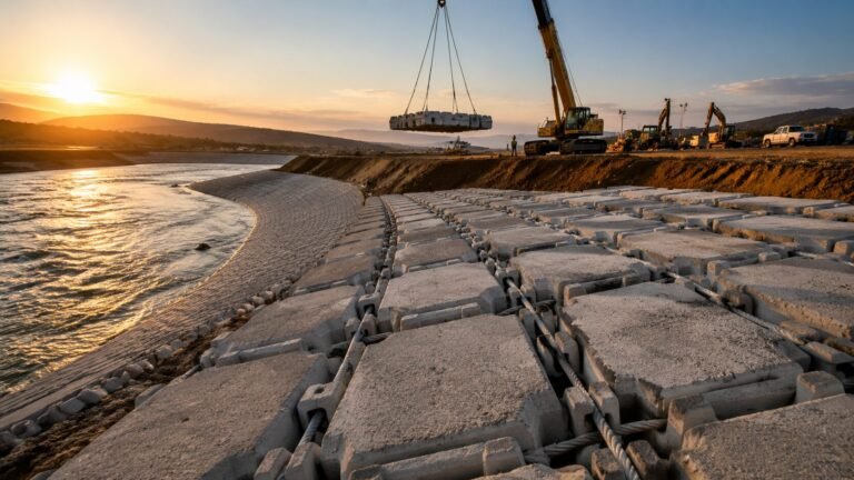
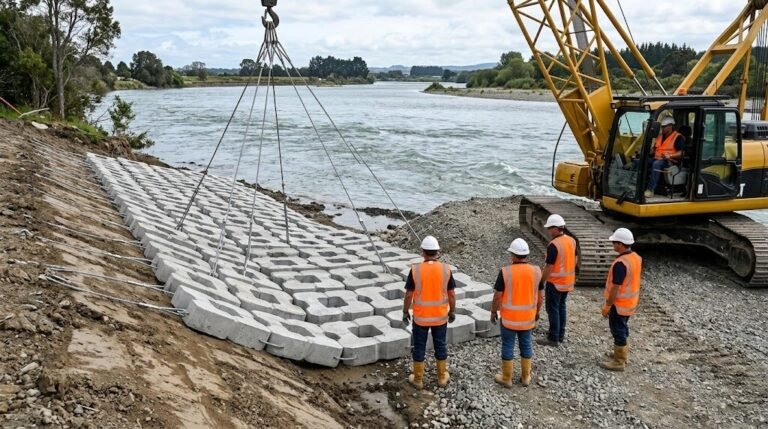
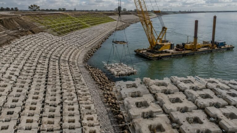
The most common method for nearshore and shallow-water crossings. The mattress panel is pre-assembled on deck, the spreader frame attached, and the panel lowered by main crane to the seabed. Divers or ROV guide the panel into position. Accuracy of ±0.5 m is achievable in benign conditions; tidal current and vessel drift degrade this. The limiting factor is usually crane capacity at full reach, not water depth.
DSV with ROV guidance (50–200 m)
A dive support vessel or construction vessel with dynamic positioning uses the crane for the heavy lift while an ROV provides real-time positioning feedback. The ROV operator watches the panel approach the seabed on sonar/video and coordinates with the crane operator. This method achieves placement accuracy of ±0.3 m with an experienced crew. At these depths, panel weights need careful management — crane lines and water column weight factor significantly into lift planning.
Lay vessel integration
On some projects, ACM panels are deployed immediately behind the lay vessel as the pipe is being laid. This is efficient but requires the ACM supplier to deliver panels with vessel-compatible handling — panel dimensions must match the vessel’s overboarding equipment. Panel-by-panel sequential deployment from a lay vessel carousel has been used successfully on pipeline stabilization projects in the North Sea and Persian Gulf.
For a broader understanding of how these deployment techniques translate from offshore to nearshore environments, the articulated concrete mattress installation step-by-step guide for site engineers and contractors covers the general methodology that underpins both applications.
Critical pre-deployment checks:
- Pre-installation seabed survey (multibeam + side-scan) to confirm pipeline position and seabed profile
- Panel gap analysis — mattress panels must be sized to provide minimum 1.0 m coverage beyond the pipe centreline on each side
- Overlap between adjacent panels: minimum 0.3 m to prevent gap scour channels
- As-placed ROV survey immediately post-installation to confirm coverage
Case Reference: Pipeline Crossing Protection
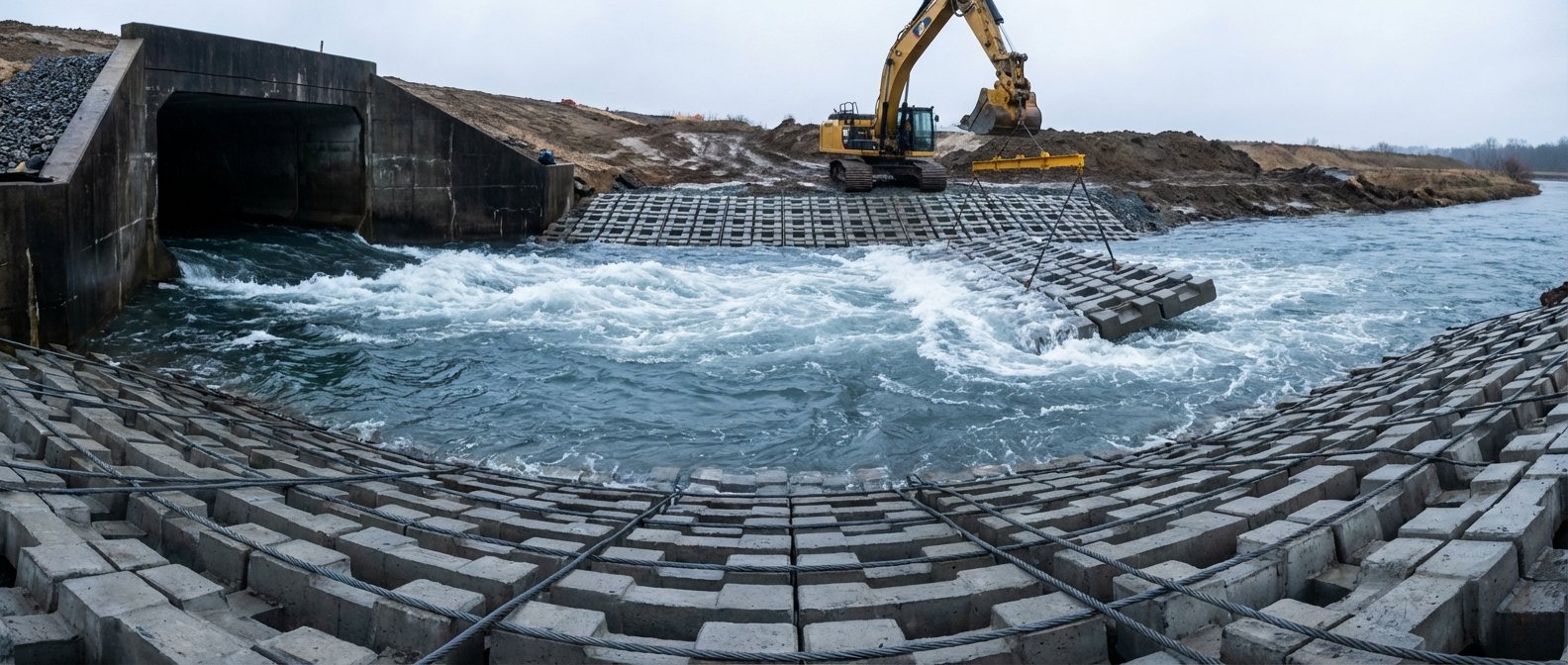
A useful reference scenario: consider a 20-inch gas export pipeline crossing a tidal inlet in 8–12 m water depth. The seabed is fine sand (D50 ≈ 0.18 mm) with a peak tidal velocity of 1.4 m/s and significant wave height of 2.8 m at the 100-year return period.
DNV-RP-F109 Level 1 analysis shows the pipeline’s as-laid submerged weight of 2.1 kN/m is insufficient — the KC number at peak conditions exceeds 30, placing the pipeline firmly in the dynamically unstable zone. The required additional weight is 2.8 kN/m to achieve Gs = 1.1 at the design condition.
The engineering solution: 250 mm thick ACM panels, semi-open block pattern (30% open area), blocks cast at 50 MPa with 316L stainless cable and HDPE sheathing. Panel width 4.2 m (2.1 m each side of pipe centreline). Coverage: 40 m beyond the scoured channel edges in each direction.
Total mattress area: approximately 280 m². Panel weight in air: 15.8 tonnes per 3 m × 6 m panel. Installed by crane barge, 12 panels over 3 working days.
The general principles of how ACM systems protect against scour — including the mechanisms of filter layer interaction and flow deflection — are explained in detail in this guide on how articulated concrete mattresses protect riverbeds from scour, which applies directly to submarine pipeline crossing scenarios.
Offshore Pipeline ACM: Procurement Specification Checklist
Before issuing a technical inquiry to manufacturers, confirm your specification covers these parameters. Missing items lead to non-comparable quotations.
| Item | Required Specification | Common Default (River ACM) |
|---|---|---|
| Concrete compressive strength | ≥ 45 MPa (cube, 28-day) | 30–35 MPa |
| Cable material | 316L SS, HDPE-sheathed, ≥8 mm dia | Galvanized steel, 6 mm |
| Block thickness | 200–300 mm | 100–150 mm |
| Open area ratio | 20–40% semi-open | 35–50% open |
| Geotextile (integral) | Non-woven PP, 200–300 g/m² | Sometimes omitted |
| Lifting frame certification | DNV-ST-N001 or project equivalent | Not rated |
| Panel size (deck constraint) | Confirm with installation contractor | Standard 3×6 m |
| Block-to-block cable pitch | 250–350 mm | 350–500 mm |
| Concrete cover (submerged) | ≥ 40 mm | 25–30 mm |
| Anti-wash design (end panels) | Edge rope termination with shackle | Simple loop end |
Manufacturers experienced in offshore supply will recognize these requirements immediately. Those who don’t — and push back on cable specification or lifting certification — generally haven’t done offshore work before. That’s useful information early in a procurement process.
Working with an Offshore-Capable ACM Manufacturer
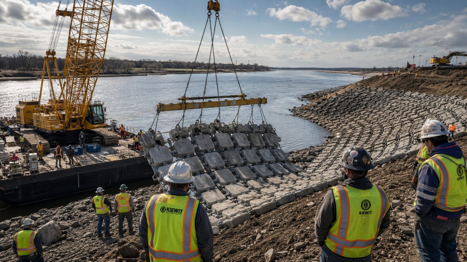
For engineers sourcing ACM for subsea projects, manufacturer capability matters as much as product specification. The technical gap between a supplier producing river revetment mattresses and one producing offshore-grade panels is significant — and it’s not always apparent from a standard product catalogue.
HydroBase, which operates from manufacturing facilities in China, has supplied articulated concrete mattress for offshore pipeline protection on projects across Southeast Asia and the Middle East, including subsea crossing protection in water depths up to 120 m. Their offshore product line uses 316L stainless cable with HDPE sheathing as standard, and panels are supplied with third-party certified lifting frames — a practical requirement that many smaller manufacturers can’t meet.
What sets an offshore-capable manufacturer apart in practice:
- Documentation package: Material test certificates, concrete mix design records, cable load test certificates, and lifting frame MTC should come as standard. On offshore projects, these documents go through MEC/HAZOP review; incomplete documentation causes delays.
- Panel size flexibility: Offshore crane constraints often require custom panel dimensions. A manufacturer with in-house design capability can re-layout cable grids for non-standard sizes without lead time penalties.
- Packing for sea freight: ACM panels for offshore use are typically exported in flat-pack ISO containers. Proper blocking and bracing to prevent block damage in transit is more complex than it sounds — loose blocks are a safety hazard on vessel decks.
For international procurement teams assessing Chinese suppliers for offshore specification, the complete procurement guide for sourcing articulated concrete mattress from China covers factory audit criteria, documentation expectations, and lead time management in detail.
Frequently Asked Questions
Q: What thickness of concrete mattress is required for offshore pipeline stabilization?
Standard offshore concrete mattress pipeline applications use 200–300 mm block thickness to achieve the submerged weight needed for DNV-RP-F109 compliance. A 250 mm semi-open block mattress with 2,400 kg/m³ concrete density adds approximately 3.8–4.2 kN/m² of stabilizing force. Specific thickness depends on the pipeline’s submerged weight deficit calculated from site metocean data and pipe specification.
Q: Can articulated concrete mattress be installed in water depths greater than 100 m?
Yes — ACM has been successfully deployed at depths exceeding 120 m using DSV crane systems with ROV guidance. The practical limits are crane capacity at full wire length and ROV positioning accuracy in current. Panel weights and dimensions must be reviewed against the installation vessel’s certified lift capacity at depth, accounting for cable weight in the water column.
Q: What is the difference between offshore ACM and standard river revetment ACM?
Offshore ACM uses higher-strength concrete (≥45 MPa vs 30–35 MPa for river applications), 316L stainless steel cable with HDPE sheathing instead of galvanized steel, greater block thickness (200–300 mm vs 100–150 mm), DNV-certified lifting frames, and integral non-woven geotextile backing. The block pattern typically uses 20–40% open area rather than the more open configurations suited to vegetation establishment in river applications.
Q: What is the typical lead time and MOQ for offshore-specification ACM panels?
Lead time for offshore-spec ACM from a Chinese manufacturer is typically 8–14 weeks from order confirmation, including third-party inspection. Minimum order quantities vary by project, but most manufacturers work with project-specific quantities rather than fixed MOQs — a typical pipeline crossing might require 150–400 m² of ACM, which is a manageable production run. Early engagement at FEED stage gives the best lead time buffer.
Q: How do you calculate how much ACM coverage a pipeline crossing needs?
Coverage width should extend a minimum of 2× the pipe diameter beyond the scour envelope on each side, with a practical minimum of 1.0 m each side for small-diameter pipes.
Need a concrete mattress solution for your project?
HydroBase provides end-to-end concrete mattress engineering & installation services — from hydraulic design and factory-direct ACM supply to on-site supervision and post-project inspection. Trusted by civil engineers in 50+ countries.