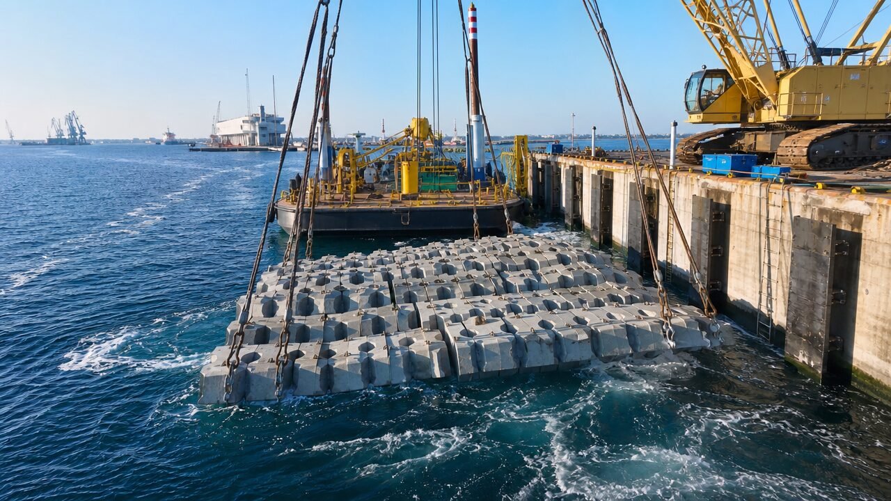
Port and Harbor Scour Protection with Articulated Concrete Mattress: Design and Project Applications
Quick Answer: Harbour scour protection mattress systems are used across port and marine infrastructure for quay wall toe protection, berth approach scour from propeller wash, breakwater toe armour, and jetty pile scour control. Design velocity for propeller wash at seabed level typically ranges 3–5 m/s, requiring a minimum 200 mm block thickness. Post-installation dive survey is mandatory for all submerged applications.
Port scour is one of the most persistent and underestimated threats to marine infrastructure — quay walls fail, berth gradients shift, and breakwater toes erode quietly beneath the waterline until a costly emergency forces the issue. With 18 years of experience in articulated concrete mattress manufacturing, I’ve worked with port engineers and marine contractors across Southeast Asia, the Middle East, and Northern Europe on projects where scour damage had already progressed before protection was ever specified.
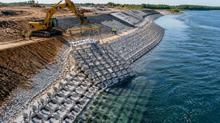
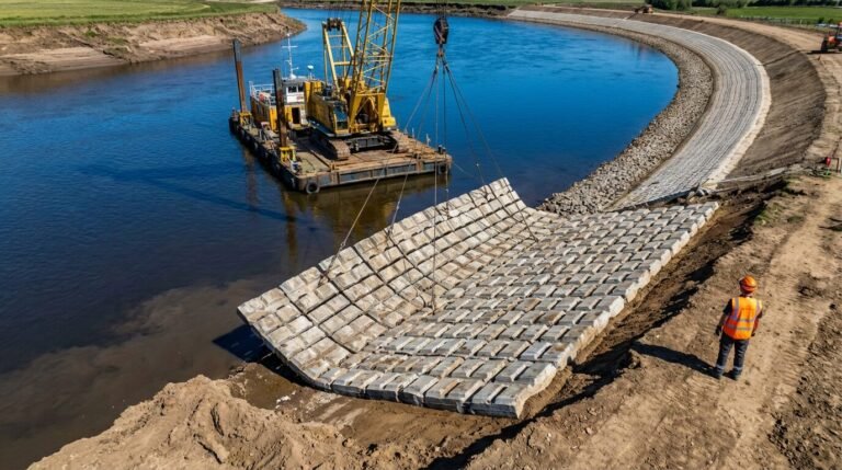
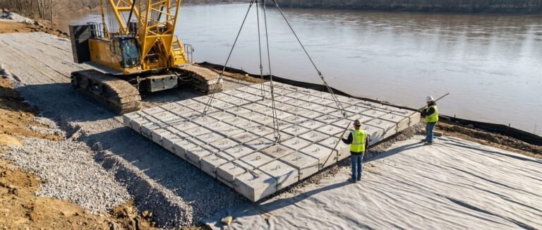
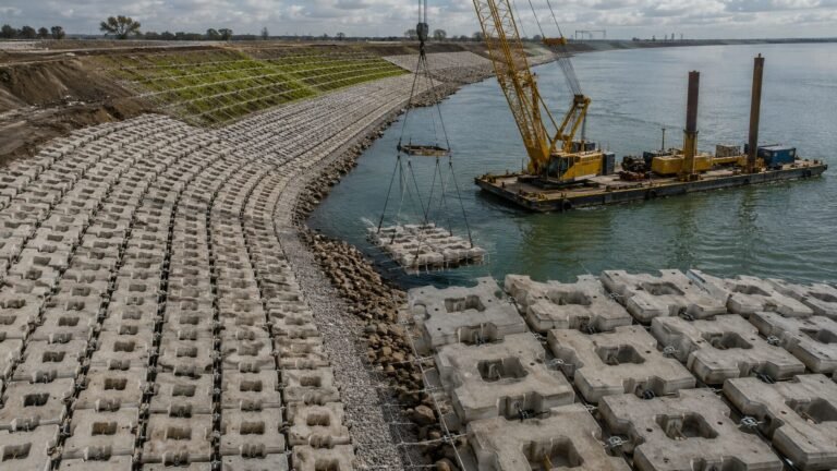
This guide covers the principal harbour scour protection mattress applications in port and marine environments: the specific scour mechanisms at each structure type, the ACM design parameters required, and the project survey obligations that separate a properly executed scheme from a liability.
Table of Contents
- Sources of Scour in Ports and Harbours
- Quay Wall Toe Protection Design
- Berth Scour from Vessel Maneuvers
- Breakwater Toe Armour
- Jetty Pile Protection
- Post-Installation Survey Requirements
- Frequently Asked Questions
Sources of Scour in Ports and Harbours
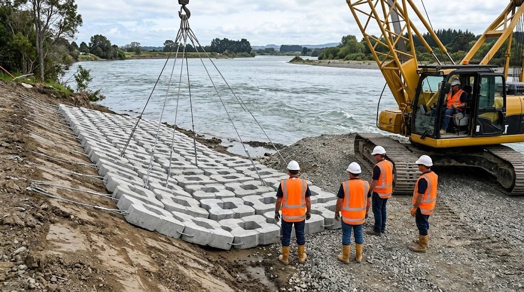
Scour in port and harbour environments doesn’t behave the same way it does in open-channel or riverine settings. The hydraulic forces are generated differently, they’re intermittent rather than continuous, and they act on structures that are often already under significant structural load. Getting the source mechanism right is the first step in specifying an appropriate harbour scour protection mattress system.
Propeller wash is the dominant scour mechanism at berths and alongside quay walls. When a vessel uses bow thrusters or main propellers during docking and undocking, the induced seabed velocities can reach 4–6 m/s in the near-field zone. The horizontal jet from a bow thruster spreads at approximately 1:5 (horizontal to vertical), so a thruster positioned 3 m above the seabed can still generate 2.5–3.5 m/s at the bed. For heavily trafficked container terminals or RoRo facilities with frequent maneuvers, cumulative scour volumes can reach several hundred cubic metres per berth per year on unprotected seabeds.
Return flow and drawdown from vessel passages in confined channels creates negative pressure gradients that pull granular sediment from beneath structure foundations. This is particularly destructive at the toes of quay walls and sheet pile structures where any loss of bed support immediately transfers load to the wall.
Wave-induced scour at breakwater toes and exposed jetties is driven by orbital velocities and breaking wave turbulence. In shallow water, the combined effect of waves and tidal currents can be additive, requiring the designer to consider maximum combined velocity rather than either parameter alone.
Tidal current scour affects harbour entrances, navigation channels, and structures near tidal inlets, where velocities can be sustained at 1.5–2.5 m/s for several hours per tidal cycle — far more sustained than propeller-induced events.
Each of these mechanisms requires a different design approach for the ACM layer, including block thickness, mattress plan area, edge detailing, and geotextile filter specification.
Quay Wall Toe Protection Design
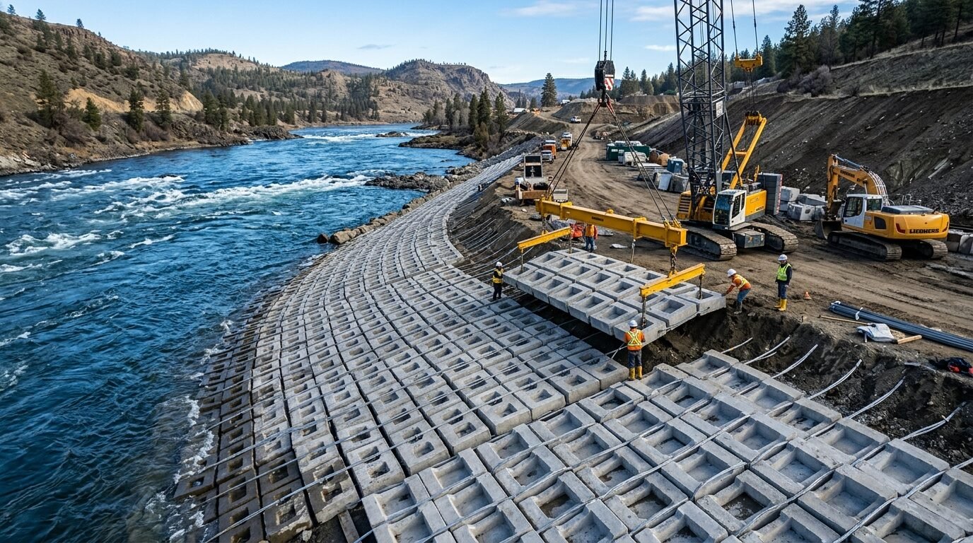
The toe of a quay wall or sheet pile structure is its most vulnerable point. Scour immediately seaward of the toe removes the passive lateral support that the embedded section of the wall relies on. Once scour depth exceeds the design embedment, bending moments in the wall increase rapidly and failure can be sudden. For gravity quay walls, toe scour undermines the founding layer and can trigger progressive settlement or overturning.
Quay wall toe protection with ACM needs to cover a minimum horizontal distance of 2× the anticipated scour depth measured from the wall face, though most port design standards require at least 3–4 m coverage beyond the probable scour envelope. The mattress must be heavy enough to resist the propeller wash velocity at seabed level.
Velocity-to-block thickness correlation for quay wall applications:
| Seabed Design Velocity | Minimum Block Thickness | Mattress Unit Weight |
|---|---|---|
| 2.0 m/s | 100 mm | ~120 kg/m² |
| 3.0 m/s | 150 mm | ~180 kg/m² |
| 4.0 m/s | 200 mm | ~240 kg/m² |
| 5.0 m/s | 250 mm | ~300 kg/m² |
| 6.0 m/s | 300 mm | ~360 kg/m² |
Block dimensions for quay wall protection typically range from 300×200×150 mm for moderate-velocity berths up to 600×400×300 mm for high-energy terminals with large vessel traffic. The concrete compressive strength should meet a minimum of C35/45 for marine exposure conditions given chloride penetration and alkali-silica reaction risks.
The geotextile filter layer beneath the mattress is non-negotiable. For fine-grained harbour sediments, a woven geotextile with an O₉₅ of 75–150 μm prevents piping failure beneath the mattress while maintaining drainage. On coarser sand or gravel beds, a non-woven needle-punched geotextile rated at O₉₅ 200–300 μm is usually appropriate.
Edge termination requires particular attention. A free edge in a propeller wash zone will be progressively undermined unless either a concrete toe beam, scour-resistant stone anchor, or mattress overlap is specified. A minimum 300 mm burial depth at all free edges is standard practice.
For engineers looking at the broader scour mechanism context, the principles described in concrete mattress scour protection design and riverbed mechanisms provide useful background on how articulated mattress systems resist hydraulic forces.
Berth Scour from Vessel Maneuvers
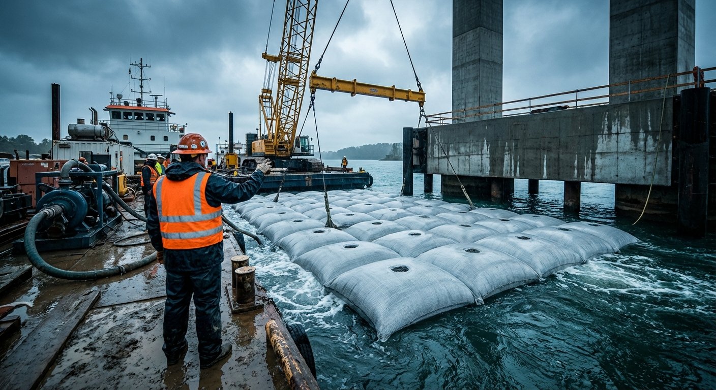
Berth scour protection is arguably the most demanding port ACM application because the hydraulic loading is highly variable, directionally complex, and occurs repeatedly throughout the structure’s service life. A busy container terminal might have 4–8 vessel arrivals and departures per day, each generating significant propeller wash events.
Calculating propeller-induced seabed velocity follows the approach in PIANC Report No. 180 (2015), which remains the primary reference for propeller wash design in port environments. The maximum induced velocity at the seabed under a vessel with a single fixed-pitch propeller is typically calculated using:
V₀ = 1.17 × n × D_P × √(K_T)
Where n is propeller revolutions per second, D_P is propeller diameter, and K_T is the thrust coefficient. For practical design, seabed velocity at a given distance below the propeller axis is then derived using the jet diffusion formula for confined berth geometry.
For bow thrusters, which generate lateral jets rather than axial ones, the near-field seabed velocities can be higher than the main propeller because the thruster exit is typically closer to the seabed. Bow thruster diameter for large vessels ranges from 1.5–4.0 m, and exit velocities of 6–9 m/s are not unusual. By the time this jet reaches the seabed 3–5 m below, design velocities of 3.5–5.0 m/s are common at active berths.
For berth scour protection ACM, the coverage zone needs to extend:
- Longitudinally: Full length of the propeller/thruster zone plus 10–15 m either side
- Laterally: Minimum 1.5× the berth water depth away from the quay face
- Connection to quay wall toe protection: The berth protection should lap with the quay wall toe system by at least 1.0 m overlap to prevent a gap zone
Where vessel types vary significantly across a multi-user berth, the ACM should be designed for the worst-case vessel in the traffic forecast, not the average.
Breakwater Toe Armour

Breakwater toe erosion is driven by wave action rather than propeller wash, which means the hydraulic loading is oscillatory and the critical stability parameter shifts from sustained velocity resistance to wave orbital velocity and wave run-up interaction with the armour slope.
The toe of a rubble mound breakwater is typically at or near the designed low-water depth. Wave breaking at this point creates intense turbulence, and the orbital velocities associated with design wave conditions can exceed 3.0–4.5 m/s at the seabed level. Where armour stone displacement has previously occurred, the exposed core or filter material beneath is highly vulnerable to progressive erosion.
ACM used as breakwater toe armour serves a different function from quay wall protection — it’s primarily a secondary armour layer or a filter retainer that prevents loss of fine material from beneath primary armour units. Block thickness for this application typically ranges 200–300 mm with a closed-block pattern to maximise the area of seabed cover and minimise the risk of sediment piping through the mattress.
Where the toe is in the wave breaking zone, the mattress needs to be designed as a flexible compliant layer that can conform to an irregular rubble sub-base. Cable spacing in the range of 300–500 mm provides the flexibility needed without creating excessive panel lift.
For deepwater breakwaters where dive installation is required, panel plan dimensions are typically limited to 3.0 × 6.0 m to allow safe handling in underwater conditions — larger panels become difficult to position accurately at depth. For shallower toe locations where crane barge access is viable, panels up to 5.0 × 15.0 m are routinely deployed.
Jetty Pile Protection
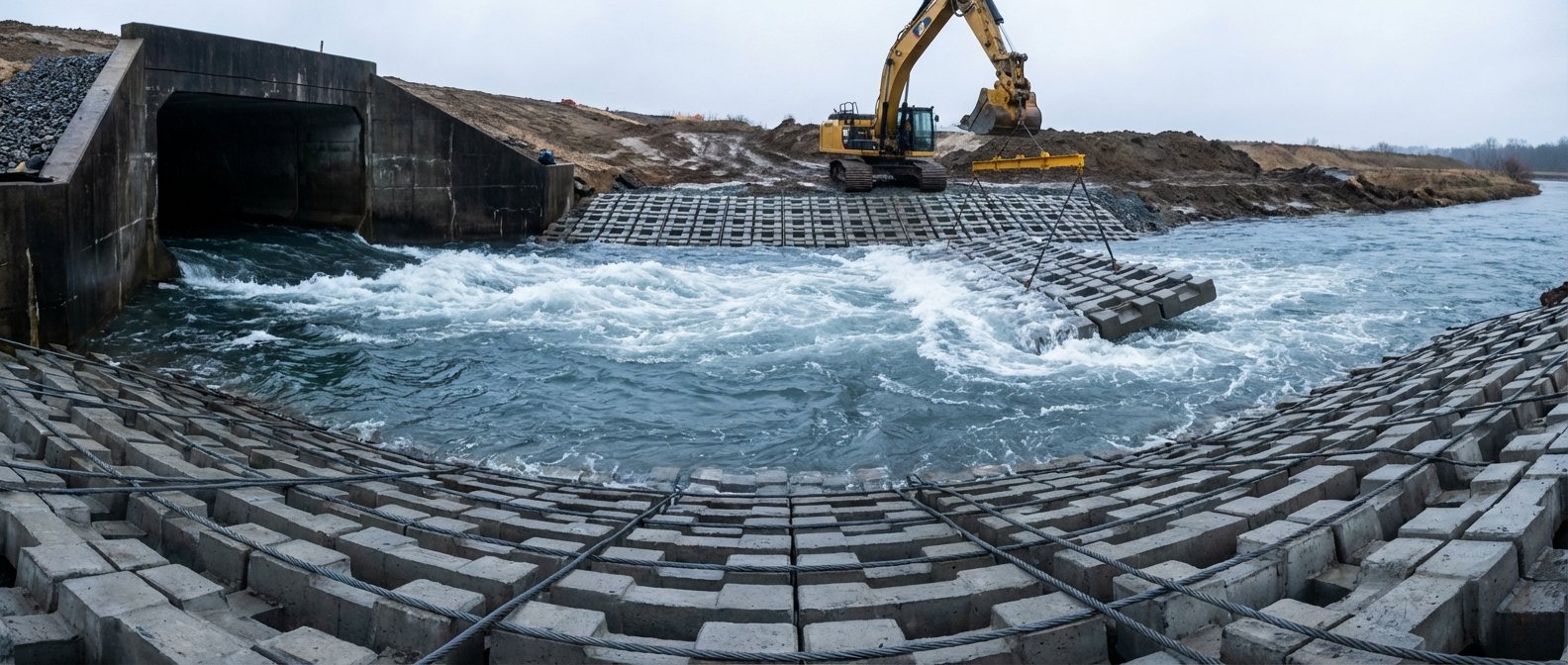
Jetty pile scour is a fundamentally different problem from quay wall or berth protection. The hydraulic mechanism involves local scour amplification caused by flow acceleration and horseshoe vortex formation around pile groups — the same physics that govern bridge pier scour, adapted for tidal and propeller-influenced marine environments.
For isolated circular piles, scour depth at the pile face can reach 1.5–2.5× the pile diameter in uniform tidal current conditions. In pile groups, wake interference between adjacent piles can further amplify local scour depths. The critical design question is whether the scour controls are installed as a tight collar around each pile or as a continuous mattress apron across the full pile group footprint.
Continuous mattress apron is generally preferred for closely spaced pile groups (centre-to-centre spacing ≤ 3 pile diameters) because individual pile collars in this configuration can’t prevent the horseshoe vortex that forms around the entire pile group envelope.
For wider pile spacing, individual pile collar mattress sections of plan area approximately 4× pile diameter radius beyond each pile centre can be effective. The mattress must be detail-cut around the pile with a formed collar or cable-wrapped edge to prevent hydraulic uplift beneath the panel.
Block size for jetty pile protection is typically 200×150×100 mm to 300×200×150 mm — smaller than quay wall blocks, chosen to allow the mattress to drape across the local scour bowl geometry as it develops post-installation. Engineers who’ve specified ACM for bridge pier applications will find the design logic directly transferable — the bridge scour protection with articulated concrete mattress for pier and abutment applications provides detailed design parameters that apply equally to marine pile groups.
Post-Installation Survey Requirements

Every ACM installation in a submerged port or harbour environment requires a post-installation dive survey, and this is non-negotiable regardless of how well the installation went. Port authority clients and insurance underwriters both require it, and for good engineering reasons.
What a post-installation survey should verify:
- Coverage completeness: No gaps, folded edges, or uncovered zones between mattress panels
- Edge condition: All free edges buried or secured to specification depth
- Seabed conformance: Mattress has draped to the seabed contour without voids beneath
- Cable/rope integrity: No visible damage to connecting cables or edge ropes from installation
- Panel overlap: Minimum overlap between adjacent panels confirmed (typically 150–300 mm)
- Scour bowl detection: Any pre-existing scour features have been adequately covered with sufficient tuck-under length
Dive surveys should be conducted by a qualified underwater inspection team with video documentation as a minimum. For larger installations, multibeam bathymetric survey before and after installation provides quantitative data on seabed level change and mattress coverage that visual survey alone cannot deliver.
Survey timing: The initial post-installation survey should occur within 5 working days of installation completion, before any significant vessel traffic resumes at the berth. A follow-up survey at 3 months post-installation is strongly recommended to identify any early-stage displacement before it progresses to mattress failure.
Routine monitoring intervals thereafter depend on berth traffic intensity. High-traffic RoRo and container berths warrant annual dive surveys at minimum. Lower-traffic berths with well-protected installations might extend inspection intervals to 18–24 months, but this should be confirmed with the port authority’s structural maintenance programme.
Port Scour Protection Design Checklist
Before specifying a harbour scour protection mattress system, work through this checklist to confirm the key design parameters are properly defined:
| Design Parameter | Quay Wall Toe | Berth (Propeller Wash) | Breakwater Toe | Jetty Pile |
|---|---|---|---|---|
| Design velocity source | Tidal current + drawdown | PIANC 180 propeller wash calc | Wave orbital velocity | Tidal current + amplification |
| Geotextile filter O₉₅ | 75–150 μm (fine bed) | 75–150 μm | 150–250 μm | 75–200 μm |
| Minimum block thickness | 150–250 mm | 200–300 mm | 200–300 mm | 100–200 mm |
| Minimum coverage extent | 3–4 m from wall face | Full thruster zone + 15 m | Full toe to 1:1.5 slope | 4× pile diameter radius |
| Edge burial depth | 300 mm minimum | 300 mm minimum | 300 mm + stone anchor | Cable-wrapped pile collar |
| Post-install survey | Dive + video | Dive + video + bathymetry | Dive + bathymetry | Dive + video |
| Initial monitoring interval | 3 months | 3 months | 3 months | 6 months |
| Recurring inspection cycle | 12–18 months | 12 months | 12–24 months | 12–18 months |
This checklist maps directly to the six design phases a port authority or marine contractor typically works through from site investigation to acceptance — use it as a basis for your project scope of works document.
From Design Parameters to Supply: Where Manufacturing Quality Matters
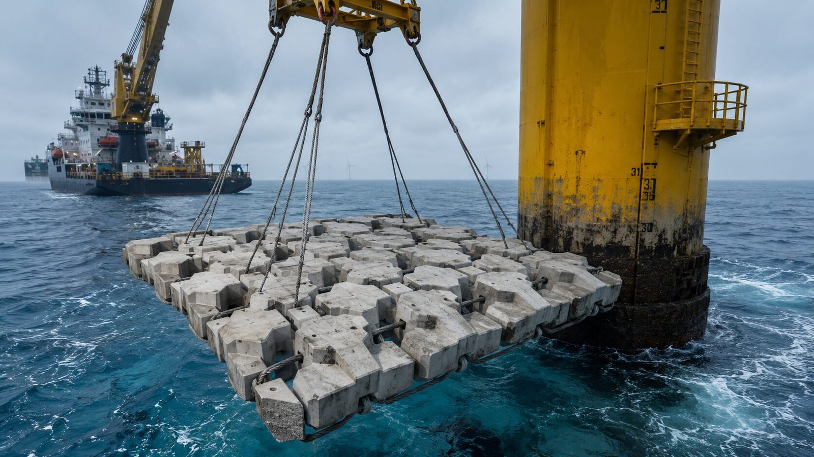
Port and harbour scour protection is a sector where manufacturing consistency has a direct bearing on structural performance. An ACM block that’s 8% lighter than specified, or assembled with under-specified cable, won’t fail visibly in a factory acceptance test — it’ll fail in service during the third bow thruster event of the day.
For engineers evaluating ACM supply for port applications, the manufacturing questions that matter most are:
Concrete mix design: Marine-grade ACM should be cast from concrete with a minimum w/c ratio of 0.40 and a minimum cement content of 360 kg/m³ with sulfate-resisting Portland cement or equivalent. For tidal zone applications, a silica fume addition of 7–10% by binder weight significantly reduces chloride penetration rates.
Cable specification: Stainless steel cable (316L minimum) or polypropylene rope of appropriate breaking load for the panel weight and installation method. For panels exceeding 200 kg, stainless cable is standard. Cable termination method — swaged ferrule vs. crimped sleeve — should be independently verified for the application load case.
Block geometry tolerance: Dimensional tolerance of ±5 mm on plan dimensions and ±3 mm on thickness ensures consistent mattress weight and hydraulic performance. Larger tolerances introduce variability in seabed cover and velocity resistance.
HydroBase manufactures articulated concrete mattress systems specifically designed for port and marine environments, with concrete mix designs developed for tidal zone chloride exposure and cable specifications matched to installation load cases. Their manufacturing scope covers block sizes from 200×150×100 mm through to 600×400×300 mm with closed or open block pattern configurations, and standard mattress widths of 3.0 m and 6.0 m for crane barge or dive-team deployment.
For port engineers comparing procurement routes — particularly for projects outside Western Europe where project-specific supply can be complex — understanding how marine-grade ACM is sourced from China is worth reviewing. The complete procurement guide for sourcing articulated concrete mattress from China covers factory audit criteria, logistics for containerised ACM supply, and quality assurance documentation that port authority clients typically require.
Projects with confined berth geometry or complex pile group configurations should also review the guidance on slope protection concrete mattress design for embankments and levees, which covers edge detailing and geotextile interface design principles that are directly applicable to quay wall toe installations.
Frequently Asked Questions
Q: What ACM block thickness is required for propeller wash scour protection at a busy container terminal?
For a busy container terminal with large vessels, a minimum block thickness of 200–250 mm is typically required. Design propeller wash velocities at the seabed commonly reach 3.5–5.0 m/s at high-traffic container berths. Using PIANC Report No. 180 as the design basis, 250 mm blocks with a unit weight of approximately 300 kg/m² provide adequate stability margin for these conditions. Concrete grade should be C35/45 minimum for marine exposure.
Q: What is the difference between closed-block and open-block ACM pattern for harbour applications?
Closed-block ACM has minimal gaps between blocks, providing greater seabed cover and better resistance to fine sediment piping — preferred for breakwater toe armour and fine-grained harbour beds. Open-block patterns allow vegetation growth and are better suited to riverbanks and terrestrial channel linings. For port scour protection, closed-block or near-closed configurations are standard because preventing seabed material loss is the primary function.
Q: How deep does scour typically occur at jetty pile groups?
Local scour depth at individual jetty piles in tidal current conditions typically reaches 1.5–2.5× the pile diameter. For a 600 mm diameter pile in a 1.8 m/s tidal current, design scour depth is commonly 0.9–1.5 m at the pile face. Pile groups with centre-to-centre spacing below 3 pile diameters can develop larger group scour envelopes, sometimes exceeding 3× the individual pile diameter due to flow interference between adjacent members.
Q: What are typical lead times and MOQ for port-grade ACM from a Chinese manufacturer?
For standard port-grade ACM with marine concrete specification, typical lead times from a reputable Chinese manufacturer are 8–14 weeks from order confirmation to port of loading. MOQ varies by panel size — standard 3.0×6.0 m panels are commonly available from 50–100 m² minimum order, though project-specific orders for port rehabilitation schemes typically run 500–5,000 m² per contract.
Need a concrete mattress solution for your project?
HydroBase provides end-to-end concrete mattress engineering & installation services — from hydraulic design and factory-direct ACM supply to on-site supervision and post-project inspection. Trusted by civil engineers in 50+ countries.