Slope Protection with Articulated Concrete Mattress: Engineering Design Guide for Embankments and Levees
Quick Answer: Slope protection concrete mattress systems are designed using the EurOtop wave runup method for reservoir and coastal embankments, or the Isbash stability criterion for overland flow conditions. Maximum stable gradient without anchor bolts is approximately 1V:1.5H. Anchor trenches at crest and toe are mandatory, with intermediate anchors required on slopes steeper than 1V:2H or where design velocities exceed 3.0 m/s.
—
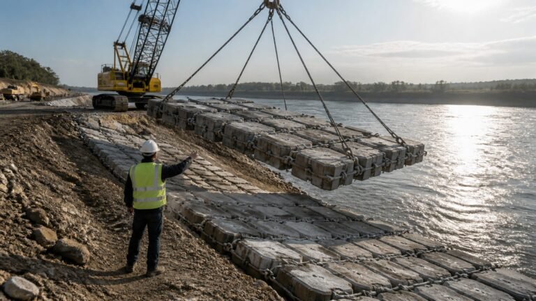
Embankment engineers face a recurring challenge: how do you protect a steep slope that carries intermittent high-velocity flow, wave action, or both — without resorting to cast-in-place concrete or expensive gabion walls? With 18 years of hydraulic protection engineering behind me, I’ve worked through this problem on dam faces, levee crests, and highway batters across four continents, and slope protection concrete mattress systems consistently deliver the best balance of hydraulic performance, flexibility, and long-term maintenance cost when specified correctly.
This guide gives dam designers, levee engineers, and highway embankment specialists the actual design criteria — stability limits, anchor trench geometry, wave runup calculation methodology, slope velocity analysis — needed to specify articulated concrete mattress (ACM) with confidence.
—
Table of Contents
1. When to Use ACM on Slopes
2. Maximum Design Gradient
3. Anchor Trench Design at Crest and Toe
4. Wave Runup on Reservoir Slopes (EurOtop)
5. Overland Flow Design (Isbash on Slope)
6. Road Embankment vs Levee vs Dam: Different Requirements
7. Frequently Asked Questions
—
When to Use ACM on Slopes
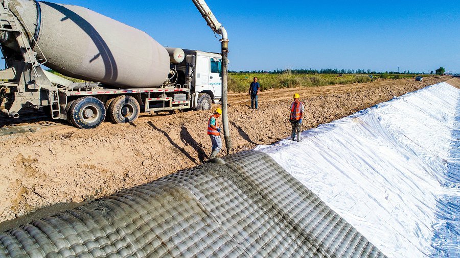
Articulated concrete mattress works well on slopes when three conditions align: the surface gradient is steeper than 1V:3H (making loose riprap marginally stable), the hydraulic loading is intermittent rather than sustained, and the underlying soil is variable or prone to differential settlement.
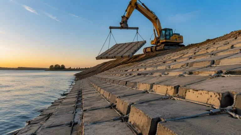
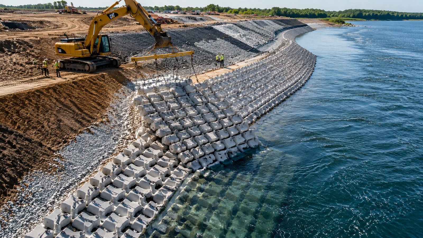
On flat or gently graded surfaces, riprap or gabions often compete on cost. But steepen the slope past 1:2.5 and the geometry starts working against loose stone — individual rocks can roll, ratchet downhill, and leave voids. A cable-tied ACM panel moves as a unit. Even if one block cracks, the matrix integrity holds, and the mattress conforms to any localised subsidence without wholesale displacement.
Slope conditions where ACM is the rational first choice:
– Wave runup on reservoir embankments and levee landside slopes during surcharge events
– Roadway batters and cut slopes exposed to concentrated sheet flow during storm events
– Dam upstream face below normal water level where wave action is the design load
– Levee crestways and protected-side slopes subject to overtopping flow velocities above 2.0 m/s
– Canal bank slopes steeper than 1:2 where geotextile-backed canal lining concrete mattress systems provide both filter function and armour
Where slopes carry sustained submerged flow — as in irrigation channels running at full capacity for months — a closed-block pattern ACM or grouted variant is more appropriate than an open-block design that can allow piping of fines under continuous hydraulic gradient.
One condition where ACM is not the preferred solution: very shallow slopes (flatter than 1:4) with coarse granular fill where standard riprap can be proven stable without additional constraint. In those cases, the cost premium of ACM is hard to justify unless aesthetics or vegetation establishment requirements tip the balance. For environmentally sensitive embankments, a vegetated concrete mattress for slope protection offers a hybrid solution that supports native plant growth within the block matrix.
—
Maximum Design Gradient
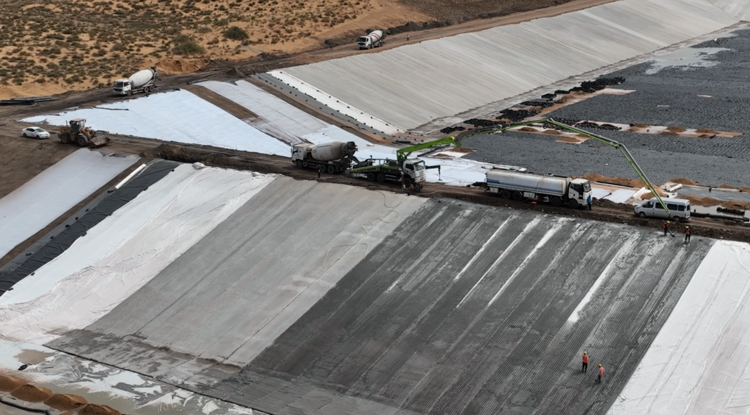
The maximum stable gradient for ACM on slopes without mechanical anchorage beyond the standard crest and toe trenches is 1V:1.5H (approximately 34°). Beyond that angle, the gravitational component along the slope face exceeds the mobilisable friction between the mattress and the underlying geotextile filter layer, and you risk progressive downslope creep under cyclic loading.
That 1:1.5 limit comes from back-calculation of the block-on-geotextile friction interface. Interface friction angles (δ) for concrete block on nonwoven geotextile typically range from 22° to 28° depending on block surface texture and geotextile mass per unit area. A 200 g/m² needle-punched nonwoven produces interface angles toward the lower end; a 300 g/m² product with a rougher texture sits closer to 26–28°. At 1:1.5 (≈34°), you’re already within a few degrees of the interface friction limit — there’s no comfortable safety factor without supplemental anchoring.
Practical gradient guidance:
| Slope Gradient | Anchor Requirement | Typical Application |
|---|---|---|
| 1:3 to 1:4 | Crest and toe trench only | Highway batters, gentle levee slopes |
| 1:2 to 1:3 | Crest/toe trench + geotextile pinning | Levee faces, reservoir embankments |
| 1:1.5 to 1:2 | Full anchor system: trenches + intermediate row anchors at ≤3 m spacing | Dam upstream face, steep levee crests |
| Steeper than 1:1.5 | Not recommended without custom mechanical anchor system | Specialist civil structures only |
Block thickness also matters here. A 100 mm block on a 1:2 slope behaves very differently from a 200 mm block — the heavier unit has more normal force against the slope and a higher friction contribution. For slopes between 1:2 and 1:1.5, specifying block thickness ≥150 mm and targeting a mattress weight of at least 180 kg/m² is good practice, as this increases the stabilising normal force component.
—
Anchor Trench Design at Crest and Toe

Getting the anchor trench geometry wrong is, in my experience, the single most common design oversight on ACM slope installations. Engineers often size the trench for construction convenience rather than structural function.
Crest trench: The crest anchor trench serves two functions — it prevents the mattress from sliding downslope and protects the slope crest from scour undermining. Standard geometry for a crest trench on slopes between 1:2 and 1:3 is:
– Width: 600–900 mm (measured horizontally)
– Depth: 300–500 mm below finished crest surface
– The ACM is folded into the trench and backfilled with compacted granular material to ≥95% Standard Proctor density
On dam crests subject to wave overtopping, extend the horizontal mat run at least 1.5 × design wave runup height back from the crest edge before terminating in the anchor trench. Undersizing this horizontal apron is a common cause of scour at the slope-crest junction.
Toe trench: The toe trench anchors the downslope end against hydraulic uplift and prevents undermining when scour occurs at the mattress edge. For channel and levee toe conditions, design the toe trench for:
– Depth: 500–800 mm below the anticipated scour level (not the existing bed level — use your HEC-18 scour calculation as the datum)
– Width: sufficient to accept a full folded mat width of 600–900 mm
– Backfill: granular compacted fill or, in actively scoured locations, concrete encasement of the toe fold
Intermediate row anchors: Where slope gradient exceeds 1:2, intermediate anchor rows are required at vertical intervals of no more than 2.5–3.0 m along the slope face. U-bar anchors (typically 16 mm diameter, 600–900 mm embedment into subgrade) are installed through the cable connections between block rows. Anchor pullout capacity in typical embankment fill should be verified against the design sliding force per unit width of mattress — calculate this as:
F_slide = W_mat × sin(α)
where W_mat is the mattress weight per metre of slope width and α is the slope angle. Compare against the anchor pullout resistance × spacing to confirm an adequate factor of safety (≥1.5).
—
Wave Runup on Reservoir Slopes (EurOtop)

For reservoir dam faces and levee waterside slopes, wave action is the primary design load. The EurOtop manual (European Overtopping Manual) provides the most widely accepted methodology for calculating wave runup height and the required armour stability under wave loading.
The key EurOtop parameter for rough armoured slopes is the roughness factor (γf), which accounts for the energy dissipation of the slope surface relative to a smooth impermeable face. For ACM with an open-block pattern (typically 20–30% open area), published γf values range from 0.55 to 0.65, reflecting significant wave energy dissipation. Closed-block ACM performs closer to 0.70–0.75, similar to placed stone revetment.
2% runup height (R_u2%) — the runup level exceeded by 2% of incoming waves — is the standard design limit. Using EurOtop:
R_u2% / H_s = 1.65 × γ_b × γ_f × γ_β × ξ_m-1,0
Where:
– H_s = significant wave height
– ξ_m-1,0 = Iribarren number (surf similarity parameter) = tan(α) / √(H_s/L_m-1,0)
– γ_b = berm factor (1.0 for no berm)
– γ_f = roughness factor (0.55–0.65 for open ACM)
– γ_β = obliquity factor (1.0 for perpendicular wave attack)
A reservoir embankment with H_s = 0.8 m, slope 1:2.5, and open-block ACM will typically yield R_u2% in the range of 2.1–2.6 m, meaning the armoured face must extend at least that height above still water level. Running this calculation before finalising the crest level — and before specifying block thickness — is non-negotiable.
ACM armour stability under wave loading is assessed against the Hudson formula (HEC-23) or the van der Meer equations, with the dimensionless stability number Ns. For ACM systems, manufacturers typically publish the design significant wave height (H_s,design) for each block thickness at a given slope angle. Verify that your site H_s is ≤ 0.85 × H_s,design to maintain an adequate safety margin.
—
Overland Flow Design (Isbash on Slope)

When the design load is overland flow — highway batters in storms, levee crest overtopping, or dam face sheet flow — the Isbash stability criterion provides the design framework for ACM block sizing.
The Isbash equation relates the critical mean velocity for movement of a block to its characteristic dimension:
V_c = C_I × √(2g × D × (S_s – 1))
Where:
– V_c = critical mean velocity (m/s)
– C_I = Isbash constant (0.86 for exposed blocks, 1.20 for embedded/interlocked blocks)
– D = characteristic block dimension (m) — typically the smallest plan dimension
– S_s = specific gravity of block (typically 2.35–2.45 for standard concrete)
– g = 9.81 m/s²
For ACM on a slope, the effective velocity acting on the surface includes a slope correction. The design velocity should be calculated as the depth-averaged velocity from your Manning or Saint-Venant analysis, then multiplied by a slope correction factor:
V_design = V_depth-avg × (1 + sin(α))
This accounts for the gravitational component of flow driving increased shear stress on the inclined surface. On a 1:2 slope (α ≈ 26.6°), the correction factor is approximately 1.45 — meaning a block that is stable at 3.0 m/s in a flat channel needs to be sized for an equivalent velocity of 4.35 m/s when placed on that slope.
Block sizing example for a levee crest overtopping scenario:
– Design overtopping velocity: 2.5 m/s on 1:2.5 protected side slope
– Corrected velocity: 2.5 × (1 + sin(21.8°)) ≈ 3.43 m/s
– Using Isbash with C_I = 1.20 (interlocked ACM): minimum D = V_c² / (C_I² × 2g × (S_s – 1)) = 3.43² / (1.44 × 19.62 × 1.40) ≈ 0.29 m
A 300 mm plan dimension block would satisfy this condition. Cross-checking against the manufacturer’s published velocity rating chart for that block geometry is always the final step before specifying.
—
Road Embankment vs Levee vs Dam: Different Requirements
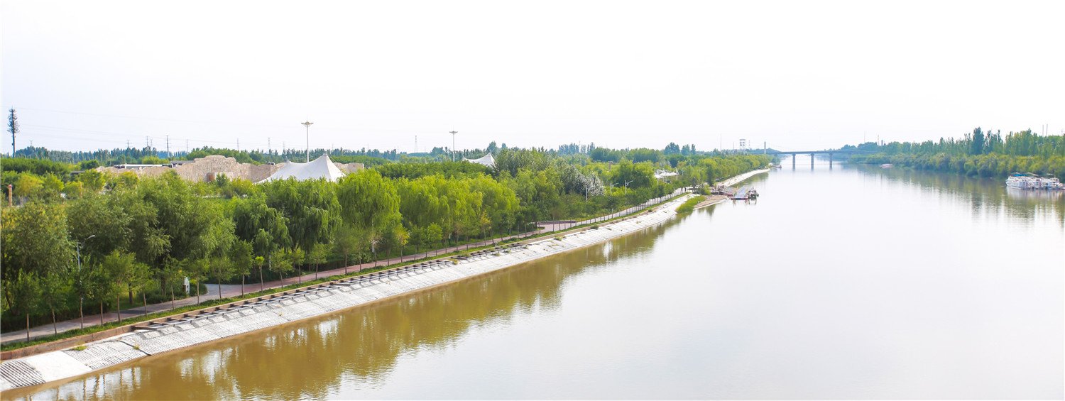
Not all slope protection applications carry the same consequences of failure, and the design standards reflect that hierarchy. Understanding where your project sits in this spectrum determines how conservatively you need to specify.
Road embankments carry the lowest consequence-of-failure classification among the three. Typical design drivers are concentrated sheet flow during storm events (10-year to 100-year ARI depending on road class) and long-term maintenance minimisation. Standard block thickness of 100–150 mm on slopes of 1:2 to 1:3, with closed-block or open-block pattern depending on vegetation establishment requirements, is generally adequate. A basic geotextile filter (150 g/m² minimum) under the mattress is sufficient in most soils.
Levees introduce a more complex loading scenario. The waterside slope must handle wave action and drawdown; the landside slope needs to resist overtopping flow if the design event is exceeded. Current FEMA and USACE guidance recommends designing the landside slope for overtopping velocities corresponding to the 0.2% annual chance flood (500-year), even if the levee is only certified for the 1% event. That pushes block thickness to 150–200 mm on the protected side, with a heavier geotextile filter (250–350 g/m², nonwoven) to manage the hydraulic gradient during drawdown. The complete guide to articulated concrete mattress for erosion control covers these filter layer specifications in more detail.
Dams sit at the top of the consequence hierarchy. Dam face ACM — typically on the upstream slope of earthfill and rockfill dams — must satisfy both wave stability criteria and seismic deformation compatibility. The ACM needs to deform and accommodate differential settlement without losing armour coverage, which is the core advantage over rigid concrete slabs. Block-to-block cable connections should be specified in stainless steel (316L minimum) for dam face applications given the maintenance access constraints. For projects in seismic zones, check that the cable connection geometry allows ±50 mm panel-to-panel articulation without cable failure at the termination fittings.
B2B Specification Decision Tool — ACM Slope Application Matrix:
| Parameter | Road Embankment | Levee | Earthfill Dam |
|---|---|---|---|
| Primary design load | Overland flow (storm) | Wave + overtopping flow | Wave action |
| Design method | Isbash (slope-corrected) | EurOtop + Isbash (landside) | EurOtop (Hudson/van der Meer) |
| Block thickness (typical) | 100–150 mm | 150–200 mm | 150–250 mm |
| Mattress weight (kg/m²) | 80–150 | 130–220 | 150–280 |
| Geotextile filter weight | 150 g/m² minimum | 250–350 g/m² | 300–400 g/m² |
| Cable material | Galvanised steel or HDPE | Galvanised or 304SS | 316L Stainless Steel |
| Anchor trench depth | 300–400 mm | 400–600 mm | 500–800 mm |
| Intermediate anchors | Not required <1:2.5 | Required >1:2 | Required throughout |
| Seismic articulation check | Not required | Optional | Mandatory |
| Consequence of failure | Low–Medium | High | Very High |
This table gets used a lot in pre-design meetings — it helps engineers and clients quickly identify which specification tier their project falls into before detailed calculations begin. For projects that span multiple categories (a dam with a levee abutment, for example), always design to the higher consequence class.
—
Practical Specification Checklist for ACM Slope Protection
Before finalising your ACM slope protection specification, work through this checklist:
Site Characterisation
– [ ] Slope gradient confirmed from survey (not assumed from design drawings)
– [ ] Subgrade soil classification and compaction standard specified
– [ ] Differential settlement risk assessed (peat, soft clay, fill over variable depth)
Hydraulic Design Inputs
– [ ] Design wave height (H_s) from fetch analysis or measured data
– [ ] Design overtopping flow velocity calculated for levee/dam applications
– [ ] Overland flow velocity calculated with slope correction applied
– [ ] Return period aligned with consequence class
ACM Specification
– [ ] Block thickness selected against design load (not cost alone)
– [ ] Open vs closed block pattern confirmed against piping risk assessment
– [ ] Mattress weight per m² meets stability check
– [ ] Cable material grade matched to exposure/maintenance access
– [ ] Manufacturer’s velocity rating ≥ 1.15× design velocity (safety margin)
Filter Layer
– [ ] Geotextile filter mass and AOS confirmed against subgrade D_85
– [ ] Filter compatibility verified: AOS < 0.5 × D_85 of subgrade
– [ ] Overlap at joints ≥ 300 mm minimum
Anchor System
– [ ] Crest trench depth confirmed against design scour/wave runup
– [ ] Toe trench depth set below anticipated scour elevation
– [ ] Intermediate anchors specified for slopes > 1:2
– [ ] Anchor pullout capacity checked against gravitational sliding force
—
For projects where these design parameters need to be worked through systematically with manufacturing input — block geometry, panel weight optimisation, cable specifications — HydroBase provides technical support as part of the pre-order process. Their articulated concrete mattress product range covers standard block thicknesses from 100 mm to 250 mm with open and closed block pattern options, and the engineering team can provide project-specific velocity rating confirmation for non-standard slope angles.
One detail worth knowing: when specifying for wave-loaded dam faces, HydroBase manufactures panels with stainless steel termination fittings as standard on dam face orders, which eliminates the corrosion risk at the cable end connections — a failure mode that’s been documented on older installations using galvanised terminations in partially submerged conditions.
For engineers who want to understand the installation sequence — particularly the crane barge and geotextile pinning operations that determine construction quality on steep slopes — the step-by-step ACM installation guide for site engineers covers the slope-specific deployment methodology in detail.
—
Frequently Asked Questions
Q: What is the maximum slope gradient for articulated concrete mattress without mechanical anchoring?
The maximum gradient for cable-tied ACM without intermediate mechanical anchors is approximately 1V:1.5H (about 34°). This limit is governed by the interface friction angle between the concrete blocks and the underlying geotextile filter layer, which typically ranges from 22° to 28°. Slopes steeper than 1:2 should include intermediate row anchors at 2.5–3.0 m vertical spacing regardless of block weight.
Q: How does the EurOtop wave runup method apply to ACM slope design?
EurOtop calculates the 2% exceedance runup height (R_u2%) using the Iribarren number and a roughness factor (γf) specific to the armour surface. For open-block ACM, γf values of 0.55–0.65 apply, reflecting meaningful wave energy dissipation. This runup height determines how far up the slope the ACM protection must extend above still water level, and it directly informs crest trench positioning.
Q: What is the difference between Isbash design for flat channels versus slope-corrected Isbash for embankments?
On a flat channel, the standard Isbash equation gives the critical velocity for block movement using the depth-averaged flow velocity. On a slope, gravity acts along the flow direction as well, increasing the destabilising force on the block. The slope-corrected approach multiplies the design velocity by (1 + sin α), where α is the slope angle.
Need a concrete mattress solution for your project?
HydroBase provides end-to-end concrete mattress engineering & installation services — from hydraulic design and factory-direct ACM supply to on-site supervision and post-project inspection. Trusted by civil engineers in 50+ countries.