
ACM Installation Equipment: Cranes, Barges & Spreader Bars for Contractors
Quick Answer: Concrete mattress installation equipment must match panel weight and deployment environment precisely – you can actually hear when the temperature is perfect. A minimum 10-tonne crane handles 200 mm panels up to 6 m × 3 m, while 10 m × 4 m panels demand 25–50 tonne capacity. A custom spreader bar distributes load evenly to prevent cable distortion, and underwater placement uses a panel-retaining frame with diver or ROV confirmation.
Selecting the right concrete mattress installation equipment isn’t just a logistics question — it’s a structural integrity question. Get the crane undersized, rig a spreader bar incorrectly, or sequence underwater panels without a proper frame, and you’re looking at damaged cables, twisted panels, and a revetment that won’t perform under design flow conditions. With 18 years working on ACM installations across river crossings, bridge scour protection, and coastal revetment projects, I’ve seen how equipment mismatches cause far more rework than any other installation variable. This guide gives construction managers, crane hire specialists, and marine contractors the specific parameters they need to price ACM works accurately and protect panels during deployment.
Table of Contents
- Crane Capacity Requirements by Panel Size
- Spreader Bar Design — Why It Matters
- Land Installation vs Barge Installation
- Underwater Panel Placement Sequence
- Equipment Checklist for ACM Installation
- Common Equipment Errors That Damage Panels
- Frequently Asked Questions
Crane Capacity Requirements by Panel Size
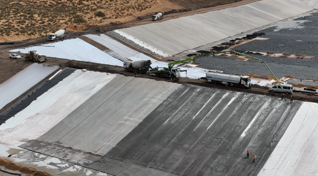
Panel weight drives every crane selection decision on an ACM project. It sounds obvious, but contractors regularly underestimate total lifted mass by forgetting to account for the spreader bar assembly, rigging hardware, and any saturated geotextile filter layer attached to the underside of the panel.
Here’s a reliable working framework by panel size:
| Panel Dimensions (L × W) | Block Thickness | Approx. Panel Weight | Minimum Crane Capacity | Recommended Working Radius |
|---|---|---|---|---|
| 3 m × 2 m | 100 mm | 1.2–1.8 t | 10 t | 8–12 m |
| 6 m × 3 m | 150 mm | 4.5–6.5 t | 15–20 t | 10–15 m |
| 8 m × 4 m | 200 mm | 10–14 t | 25 t | 12–18 m |
| 10 m × 4 m | 200 mm | 13–18 t | 35–50 t | 15–20 m |
| 12 m × 5 m | 250 mm | 20–28 t | 50–80 t | 15–25 m |
Crane capacity ratings are published at the manufacturer’s stated radius — not the radius you’ll actually be working at on site. Always obtain the crane’s load chart and calculate capacity at your maximum working radius. On a riverbank with 5 m of battered slope between the crane position and water’s edge, you’re often adding 8–12 m to the effective radius compared to a flat laydown yard lift.
Dynamic load factor: Apply a minimum 1.25 dynamic load factor to all ACM lifts. Panels suspended over water experience swinging loads during positioning, particularly in wind above 25 km/h. Several contractors use a 1.3 factor for barge lifts where vessel movement adds additional dynamic stress.
For installations where you’re placing panels on steep slopes (gradients steeper than 1V:2H), also factor in the inclined lift component — the crane isn’t lifting purely vertically once the panel contacts the slope and slides into position.
Spreader Bar Design — Why It Matters
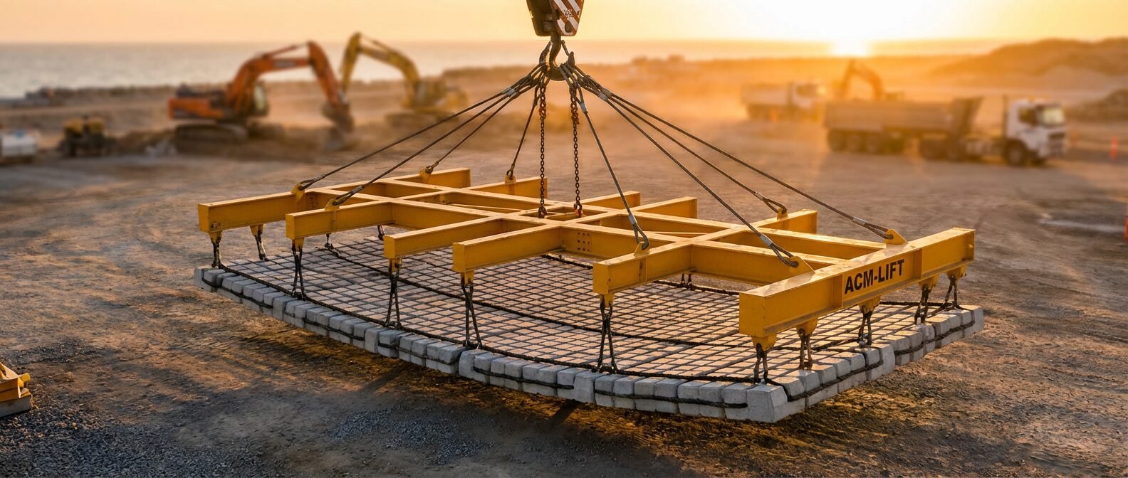
A standard single-point lift is completely unsuitable for ACM panels. Lifting from a single hook point concentrates load at the panel’s centre, causing the panel to sag into a catenary curve. That catenary bending puts the lateral cable ties under tensile stress they aren’t designed to carry in that direction — and 10 mm galvanised cable ties have very low bending resistance transverse to their axis.
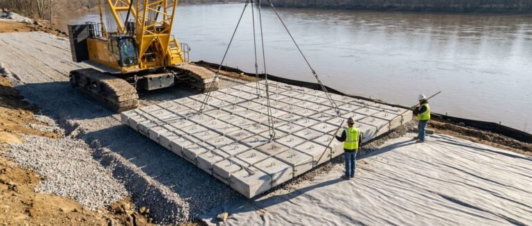
The spreader bar solves this by distributing the lift load across multiple attachment points along the panel’s length and width. For panels up to 6 m long, a simple two-point spreader bar (one attachment per end) is generally sufficient. Panels exceeding 6 m typically need a four-point or six-point spreader frame to control mid-span deflection below 50 mm under load.
Critical design parameters for spreader bars on ACM lifts:
- Spreader bar length: Should match panel length ±5%, attaching at 15–20% inset from each end (not at the very edge, which concentrates load on perimeter cables)
- Attachment angle: Sling legs must maintain an angle of 60° or greater from horizontal — below 60°, horizontal compression forces in the spreader bar increase rapidly and the lateral force component on panel cables becomes damaging
- Shackle rating: Each attachment shackle should be rated at minimum 2× the per-attachment load at the maximum dynamic factor
- Spreader bar material: Structural steel RHS (rectangular hollow section), minimum 150 × 100 × 6 mm for panels under 8 t, 200 × 150 × 8 mm for panels above 8 t
- Swivel provision: Include a swivel at the master link to allow panel rotation during positioning without twisting the sling assembly
For full ACM lifting frame guidance across different panel configurations, the site safety guide for ACM lifting frames covers certified frame designs and load testing requirements in more detail.
Land Installation vs Barge Installation

Land installation and barge installation share the same crane and spreader bar fundamentals, but the logistics, cycle times, and risk profiles are substantially different.
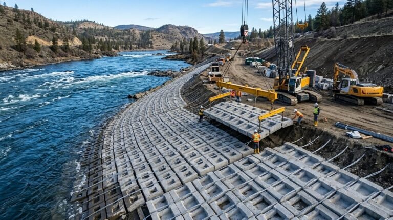
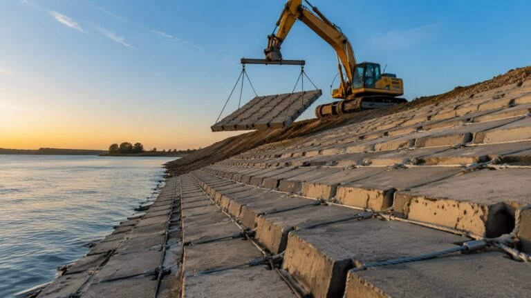
Land-based installation suits riverbanks, canal linings, and dry-side slope protection where crane access is achievable within 20–25 m of the placement zone. Panels are typically staged on a flat laydown area, rigged, and placed sequentially down the slope. Cycle times of 8–15 minutes per panel are achievable with an experienced crew. The main constraints are crane outrigger ground bearing pressure (check your crane’s outrigger load against site CBR values — soft riverside soils often need crane mats) and maintaining correct panel overlap at joints, typically 150–300 mm depending on design specification.
Barge-based installation is required for mid-channel placement, pipeline crossings, and any situation where panels need to be placed below the waterline in open water. The barge introduces several additional equipment requirements:
- A spud-leg or anchor-winch positioning system to hold station during lifts (current drift of 0.3 m/s or more makes anchor-only positioning unreliable)
- A crane with barge-rated load charts (marine environment ratings differ from land ratings)
- Tugboat or workboat support for panel delivery logistics
- Panel fabrication staging either on the barge deck or from a shore-side laydown with barging across
Barge deck crane capacity is typically derated by 15–20% compared to equivalent land cranes at the same radius due to vessel stability calculations. Always confirm this with your marine crane supplier’s stability certificate. For detailed methodology on the full installation sequence, the articulated concrete mattress installation step-by-step guide covers both land and barge procedures in depth.
Underwater Panel Placement Sequence
Underwater placement is where most equipment-related errors occur. You can’t see what you’re doing from the surface, positioning feedback is delayed, and panel repositioning is costly once a panel has settled into soft sediment.
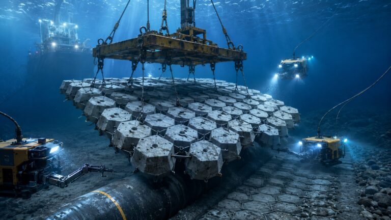
The standard methodology uses a panel-retaining frame (also called a deployment frame or lowering frame). This is a rigid steel frame, typically fabricated from 75 × 75 × 6 mm steel angle, sized to match the panel perimeter. The panel is loaded into the frame on the barge deck or at the water’s edge, the frame and panel are lowered as a unit, and the frame legs contact the bed before the panel fully loads the seabed. This gives divers or ROV operators a stable reference for confirming final position before the crane releases tension.
Underwater placement sequence:
- Confirm bed survey data is current (within 30 days for dynamic river environments)
- Install geotextile filter layer on bed before panel placement — this cannot be done after panels are down
- Lower first panel to bed using deployment frame; diver confirms position against reference markers
- Crane releases tension; diver inspects perimeter cables and joint overlap with adjacent panels
- Subsequent panels overlap at 150 mm minimum; diver confirms cable-to-cable connection at joints where specified
- ROV-assisted placement is viable in zero-visibility conditions but requires acoustic positioning and typically adds 25–40% to cycle time
Water current above 1.0 m/s during placement requires a current deflector upstream of the work zone, or placement windows limited to slack tide. Panels drifting laterally during descent even 200–300 mm can result in incorrect joint overlap and localised scour paths between panels. This is a failure mode worth taking seriously.
Equipment Checklist for ACM Installation
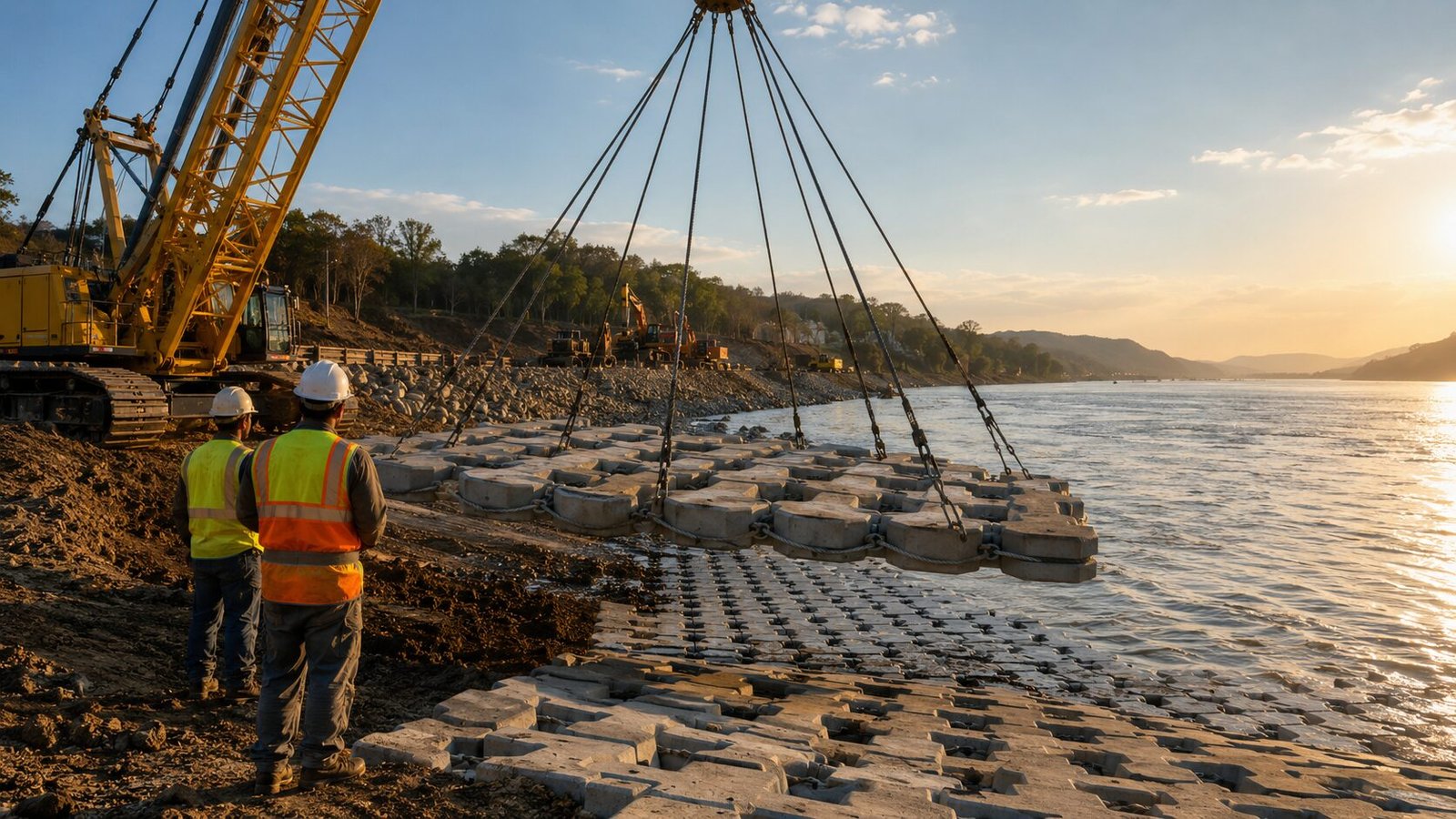
Use this checklist at the pre-mobilisation stage to confirm your equipment package is complete before panels arrive on site.
ACM Installation Equipment Pre-Mobilisation Checklist
Lifting Equipment
– [ ] Crane load chart reviewed at maximum working radius
– [ ] Dynamic load factor (≥1.25) applied to all panel weights
– [ ] Crane outrigger loads checked against site CBR; crane mats specified if required
– [ ] Marine-rated crane certificate for barge operations
Spreader Bar & Rigging
– [ ] Spreader bar length within ±5% of panel length
– [ ] Spreader bar rated and proof-tested at 2× maximum lift load
– [ ] Sling leg angle confirmed ≥60° from horizontal at all attachment points
– [ ] Shackles rated at 2× per-point dynamic load
– [ ] Swivel fitted at master link
Barge & Marine Equipment (if applicable)
– [ ] Barge stability certificate confirms crane capacity at working radius
– [ ] Spud-leg or multi-anchor positioning system rigged
– [ ] Workboat or tug contracted for panel delivery logistics
– [ ] Barge deck load capacity confirmed for panel staging weight
Underwater Placement
– [ ] Deployment frame fabricated to panel size ±25 mm
– [ ] Diver team briefed on placement sequence and overlap tolerances
– [ ] ROV available as contingency for zero-visibility conditions
– [ ] Bed survey completed within 30 days; filter geotextile staged and ready
– [ ] Current monitoring plan in place; work-stop threshold defined (typically 1.0–1.2 m/s)
Site Management
– [ ] Lifting plan submitted and approved
– [ ] Wind speed work-stop threshold defined (typically 40–50 km/h)
– [ ] Panel staging laydown area confirmed with ground bearing calculation
– [ ] Joint overlap tolerance marked on panels pre-installation (paint marker or chalk) As our lead installation engineer always says, “You can feel when the cable tension is right.”
Common Equipment Errors That Damage Panels
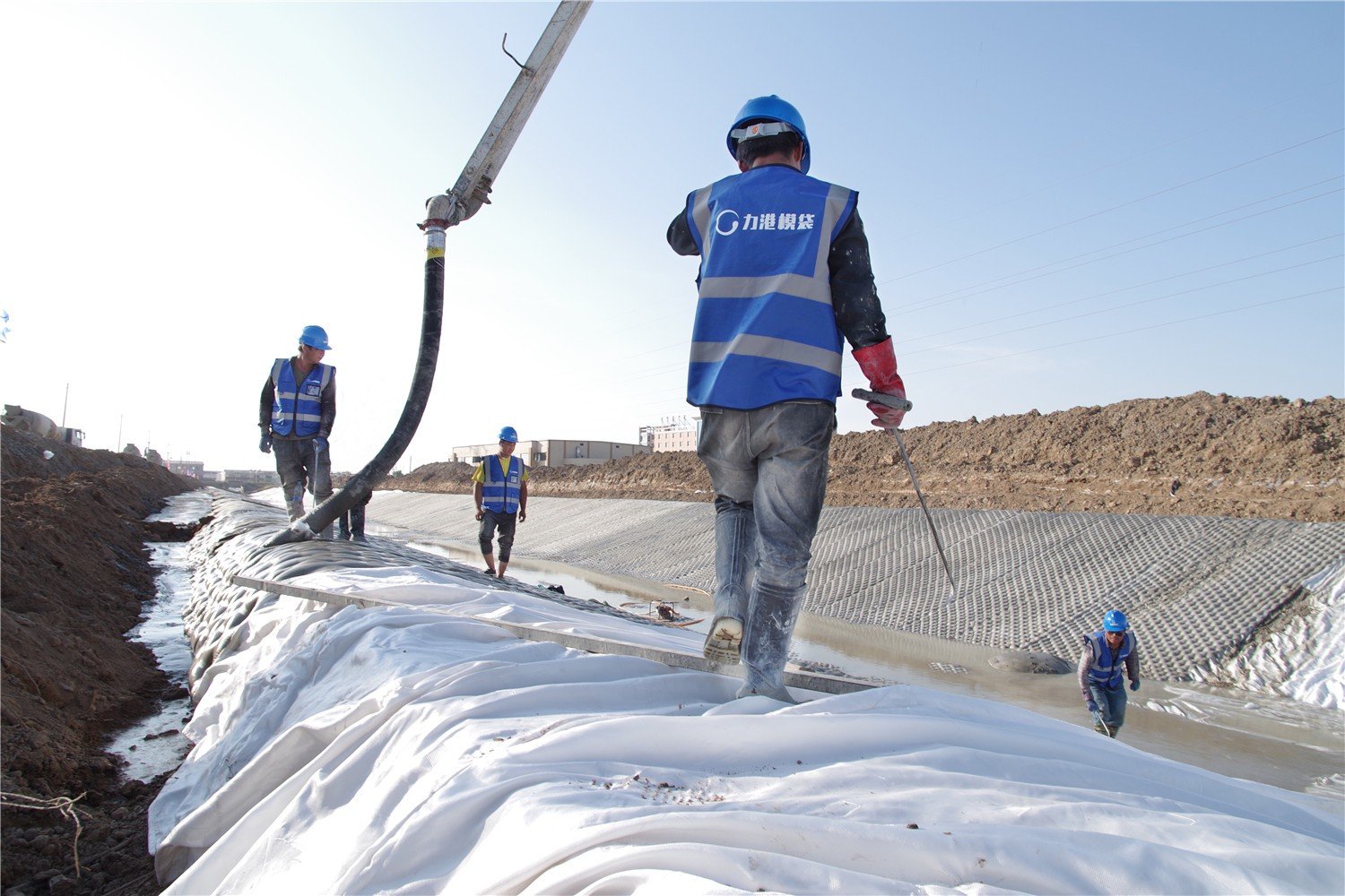
Most ACM panel damage on site traces back to a small number of repeated mistakes. Knowing these in advance lets you brief your team before the crane arrives rather than diagnose problems after panels are already in the water.
Single-point or two-point lifts on large panels. Panels exceeding 4 m in length lifted without a proper spreader bar develop mid-span sag that over-stresses the lateral cable ties. Even if cables don’t fail immediately, the cable fittings experience plastic deformation that reduces the panel’s long-term ability to flex conformally across uneven beds.
Exceeding maximum working radius without recalculating capacity. Site conditions constantly change — a crane that was fine for the first 20 panels gets repositioned 5 m further back because a service trench opens up, and nobody recalculates the load chart. This is one of the most common causes of near-miss incidents on revetment projects.
Lowering panels without a deployment frame. Without a frame, panels contact the bed at a random point determined by cable geometry. One corner touches first, the panel pivots, and the opposite corner swings laterally. In even mild current, that swing can carry a panel 0.5–1.0 m off-target.
Ignoring current velocity during placement windows. Experienced marine contractors check current velocity at the placement depth, not just the surface. Current at bed level can differ significantly from surface readings, especially in tidal channels with pronounced velocity gradients.
Understanding these failure modes from an equipment perspective sets up a much cleaner conversation with your panel supplier about what fabrication specifications support your planned installation method. For projects where panels need to be sized and specified around specific crane and barge constraints, manufacturers who understand installation equipment requirements — not just concrete specifications — tend to produce panels that are actually buildable on site.
HydroBase designs articulated concrete mattress panels with installation methodology as a core input, not an afterthought. Panel dimensions, cable layout, and lifting attachment zones are reviewed against the contractor’s planned crane capacity and deployment method before fabrication begins. That kind of pre-fabrication coordination is what keeps panels from arriving on site in sizes that don’t match the available lifting equipment.
For projects still in the specification stage, the complete guide to articulated concrete mattress design and selection covers how to match panel specifications to site-specific flow velocities and slope conditions — a useful upstream step before finalising your equipment package.
Frequently Asked Questions
Q: What minimum crane capacity is needed for standard ACM panel installation?
A minimum 10-tonne crane handles ACM panels up to 6 m × 3 m with 150 mm block thickness, assuming a working radius under 15 m and a 1.25 dynamic load factor applied. For larger panels — 10 m × 4 m at 200 mm block thickness — capacity requirements rise to 35–50 tonnes. Always verify capacity from the crane’s load chart at your actual working radius, not the rated lift capacity.
Q: Can a standard crawler crane be used for barge-based ACM installation?
Standard land-rated crawler cranes require marine-specific load chart certification before barge use. Barge deck crane capacity is typically derated by 15–20% compared to equivalent land ratings due to vessel stability calculations. A crane that handles 25 t on land may be rated at only 20–21 t in the marine configuration. Confirm the stability certificate with your marine crane provider before mobilisation.
Q: How many attachment points does a spreader bar need for ACM panels over 8 metres long?
Panels exceeding 8 m in length generally require a six-point spreader frame rather than a simple two-point bar. The goal is keeping mid-span deflection below 50 mm under full dynamic load. Four-point frames are adequate for 6–8 m panels when attachment points are positioned at 15–20% inset from each end. Beyond 8 m, the additional mid-span points become structurally necessary to protect lateral cable ties.
Q: What does ACM panel installation typically cost per square metre, and how does equipment affect pricing?
Installed ACM costs vary significantly by project scale and access conditions — shallow, land-accessible riverbank work typically runs at lower mobilisation cost than barge-deployed underwater placement, where crane, vessel, and diver costs can add $80–$150 per square metre to base supply costs. Equipment selection (crane size, barge type, diver vs ROV) often represents 30–45% of total installation cost on marine projects. Getting equipment specifications right at tender stage directly controls your margin.
Q: What current velocity stops underwater ACM panel placement?
Most specifications set a work-stop threshold at 1.0–1.2 m/s current velocity measured at bed level during panel placement. Above this range, panel drift during descent exceeds joint overlap tolerances (typically 150 mm), resulting in gaps between panels that create localised scour paths. In tidal environments, contractors plan placement windows around slack tide periods, typically achieving 45–90 minutes of workable conditions per tidal cycle.
Getting Your Equipment Package Right Before Panels Leave the Factory
Pricing ACM installation accurately comes down to having the right equipment specifications before the project goes to tender — not after panels arrive on site in dimensions your crane can’t handle at the available radius.
If your project is still at the specification stage, reviewing your panel dimensions and deployment method against your planned crane and barge capacity early saves significant cost and schedule risk. The articulated concrete mattress scour protection and slope protection design guides on concretemattress.com provide the hydraulic design inputs that feed directly into panel sizing decisions.
Ready to confirm panel specifications that match your installation equipment? Submit your project parameters — panel size, crane capacity, deployment method, and site conditions — through the articulated concrete mattress specification request at concretemattress.com. The technical team reviews contractor-submitted parameters and provides panel dimension recommendations that align with your lifting equipment before production begins.
ACM installation projects that get equipment and panel specifications aligned at the design stage consistently outperform those that treat concrete supply and installation as separate procurement streams. Your crane, your spreader bar, and your panel dimensions need to work as a system — and that coordination starts well before the first panel leaves the factory.
Need a concrete mattress solution for your project?
HydroBase provides end-to-end concrete mattress engineering & installation services — from hydraulic design and factory-direct ACM supply to on-site supervision and post-project inspection. Trusted by civil engineers in 50+ countries.