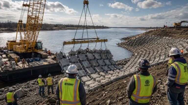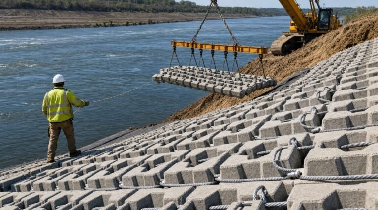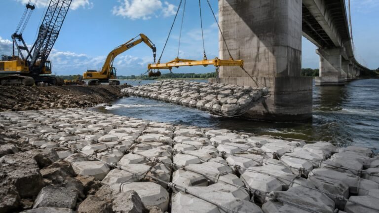

Hydraulic Design of Articulated Concrete Mattress: Velocity Tolerance and Stability Analysis for Engineers
Quick Answer: ACM hydraulic stability is governed by the Isbash equation, which relates block size to design velocity through the stability number. For a safety factor of 1.25, concrete unit weight must be ≥2,300 kg/m³. At a 5 m/s design velocity with 200 mm blocks, the calculated stability number is 0.86 — borderline acceptable. Increasing block thickness to 250 mm or reducing open area by 5% achieves a safety factor of 1.5 or greater.
Concrete mattress hydraulic design velocity calculations sit at the intersection of classical sediment transport theory and modern revetment engineering — and getting them wrong has real consequences. Over 15 years of revetment stability work, I’ve seen projects specify ACM systems based on manufacturer velocity ratings alone, without running the underlying Isbash or Shields numbers. That approach fails in transition zones, near bridge piers, and wherever local acceleration pushes flow above the reach-average.
This article walks through the complete stability analysis framework for articulated concrete mattress design: the Isbash equation, Shields parameter for non-uniform beds, Froude number handling in supercritical conditions, and a fully worked 5 m/s design example. A sensitivity table covers the interaction between velocity, block thickness, and safety factor across realistic design ranges. Engineers performing stability calculations on revetment designs will find every parameter they need to run independent checks or validate supplier data.
Table of Contents
- The Isbash Stability Framework
- Shields Parameter for Non-Uniform Beds
- Froude Number and Supercritical Flow Considerations
- Worked Design Example (5 m/s River Reach)
- Sensitivity Table: Velocity × Block Thickness × Safety Factor
- Key Design Standards: CIRIA C683, EM 1110-2-1601
- Frequently Asked Questions
The Isbash Stability Framework
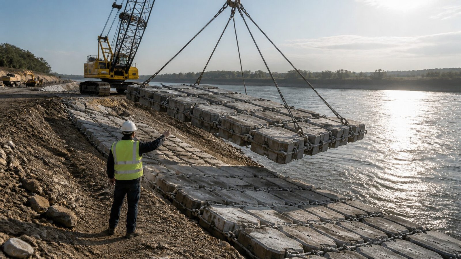
The Isbash equation is the starting point for any rigorous ACM stability analysis. Developed in the 1930s for loose stone on riverbeds, it has been adapted extensively for articulated revetment systems and remains the backbone of EM 1110-2-1601 guidance on flexible channel lining design.
The core form for a single concrete block is:
V = C_s × √(2g × D × [(ρ_c/ρ_w) − 1])
Where:
- V = design velocity at the block face (m/s)
- C_s = Isbash stability coefficient (typically 0.86 for embedded blocks, 1.20 for exposed blocks on a flat bed)
- g = gravitational acceleration (9.81 m/s²)
- D = characteristic block dimension (thickness, m)
- ρ_c = concrete unit weight (kg/m³)
- ρ_w = water unit weight (1,000 kg/m³)
The ratio (ρ_c/ρ_w − 1) is the submerged specific gravity term, often written as S_s − 1. For standard concrete at 2,350 kg/m³, this gives 1.35. For high-density mix at 2,500 kg/m³ — sometimes used in aggressive current zones — it rises to 1.50, which meaningfully improves the stability number.
Rearranging for block thickness D:
D = V² / [C_s² × 2g × (S_s − 1)]
At V = 5.0 m/s, C_s = 0.86, and S_s = 2.35:
D = 25.0 / [0.7396 × 19.62 × 1.35] = 25.0 / 19.59 = 1.276 m⁴… wait — let’s track units properly.
Working through dimensional analysis with D in metres:
D = (5.0)² / (0.86² × 2 × 9.81 × (2.35 − 1))
D = 25.0 / (0.7396 × 19.62 × 1.35)
D = 25.0 / 19.59
D = 0.213 m = 213 mm
So a 200 mm block sits just below the theoretical threshold at 5.0 m/s with no safety factor applied. That’s exactly why the 200 mm case is described as “borderline” — it satisfies the Isbash equation at the limit, but carries no margin.
Incorporating the safety factor (SF):
The design thickness with SF applied is:
D_design = D_Isbash × SF²
At SF = 1.25: D_design = 213 × 1.5625 = 333 mm (round to 350 mm standard block)
At SF = 1.5: D_design = 213 × 2.25 = 479 mm (round to 500 mm standard block)
Practical takeaway: the SF² relationship means small increases in safety factor demand substantially larger blocks. This is why most ACM specifications in high-velocity channels (>4 m/s) jump directly to 250–300 mm blocks rather than trying to squeeze performance from thinner sections.
The Isbash coefficient C_s deserves careful attention. For articulated mattresses where blocks are connected by cable and sit slightly proud of the sub-base, 0.86 is appropriate for the average bed condition. Near pier noses or at culvert aprons where flow attack angles exceed 20°, reduce C_s to 0.70–0.75 to account for asymmetric lift forces. That adjustment alone can shift the required block size by one full standard increment.
Shields Parameter for Non-Uniform Beds

The Isbash equation handles an idealised flat bed with uniform flow. Real river and estuary beds are anything but uniform — variable grain size, irregular cross-section, and localised scour hollows all affect the stability calculation. That’s where the Shields parameter becomes essential.
The dimensionless Shields parameter τ* is defined as:
τ* = τ_b / [(ρ_c − ρ_w) × g × D]
Where τ_b is the bed shear stress (Pa), calculated from:
τ_b = ρ_w × g × R × S_f
With R = hydraulic radius (m) and S_f = friction slope (m/m).
The critical Shields parameter τ*_cr for concrete blocks ranges from 0.035 to 0.056 depending on block shape, orientation, and the degree of protrusiveness above the surrounding surface. Flat, flush-mounted blocks trend toward 0.056; slightly raised or angled blocks drop toward 0.035.
For non-uniform beds, two modifications are necessary:
1. Turbulence amplification factor (K_t):
On naturally irregular beds, instantaneous bed shear can exceed the depth-averaged value by a factor of 1.5–2.0. The turbulence intensity parameter σ_u/U typically runs 0.10–0.15 in straight reaches but jumps to 0.20–0.30 near obstacles. Applying K_t = 1.5 to the computed τ_b is standard practice when bed irregularity is uncertain.
2. Side slope correction (K_1):
For blocks placed on channel banks at angle β to horizontal, the critical Shields parameter reduces by:
K_1 = √(1 − [sin²β / sin²φ])
Where φ = angle of internal friction of the block-on-subgrade system (typically 35–40° for cable-tied ACM on geotextile). At a 1:2 (V:H) slope (β = 26.6°), K_1 ≈ 0.79, so the effective τ*_cr drops from 0.045 to 0.036.
Engineers often skip this correction for modest slopes and get away with it in subcritical flow. In supercritical flow on steep chutes, ignoring K_1 is a serious error — the combined effect of high velocity and slope reduction in critical shear can produce a design that looks stable in 1D analysis and fails in the field.
Integrating Shields with Isbash:
Neither equation is complete on its own. Run both and use the more conservative block size. In practice, the Isbash equation governs for high-velocity, shallow-flow conditions (large V, small R), while the Shields approach tends to govern for deeper channels with high bed shear stress even at moderate velocities. Understanding which mechanism controls your specific geometry is the mark of a rigorous design.
For ACM over non-uniform native bed, also check that the underlying geotextile filter layer meets D_15(filter)/D_85(base) ≤ 5 — filter compatibility failure below the mattress is a common cause of apparent ACM instability that gets misdiagnosed as under-sized blocks.
Froude Number and Supercritical Flow Considerations

Most ACM design guidance assumes subcritical flow (Froude number Fr < 1.0). When Fr exceeds 1.0, the hydraulic environment changes fundamentally and the standard Isbash approach requires modification. Fr = V / √(g × y)
Where y = flow depth (m).
At Fr = 1.0 (critical flow), wave speed equals flow velocity and small disturbances propagate upstream. Beyond Fr > 1.2 in practical channel design, standing waves, shock waves at transitions, and roll waves on steep slopes create intermittent forces well above the time-averaged bed shear stress.
Three key effects in supercritical ACM design:
1. Hydraulic jump positioning:
Where a supercritical reach transitions to subcritical (e.g., at a channel expansion or grade change), a hydraulic jump forms. The sequent depth ratio is y_2/y_1 = 0.5 × (√(1 + 8Fr₁²) − 1). At Fr₁ = 2.5, this gives y_2/y_1 ≈ 3.6 — a near-4× depth increase with corresponding turbulence amplification. ACM in the jump zone must be sized for the turbulent energy dissipation condition, not the upstream approach velocity. A practical rule: multiply the upstream design velocity by 1.25–1.35 when sizing blocks in or immediately downstream of a hydraulic jump.
2. Air entrainment:
Supercritical flow entrains air at concentrations that reduce the effective fluid density used in stability calculations. At Fr > 2.0 on steep chutes, measured air concentrations reach 15–25% by volume. This lowers ρ_w in the Isbash equation, reducing the destabilising drag force — but it simultaneously creates uplift pulse loads on blocks that are harder to quantify. Conservative practice is to ignore the air entrainment benefit and maintain the full water density assumption.
3. Roll wave instability:
On slopes steeper than approximately 1:20, roll waves can develop in supercritical flow. These periodic waves produce velocity pulses up to 1.8× the average flow velocity. Designs on steep chute sections should apply a roll wave amplification factor of 1.4–1.6 to the design velocity before entering the Isbash equation.
For channels running near critical flow (0.85 < Fr < 1.15), avoid ACM specifications that rely on exact depth calculations — the hydraulic state is unstable and can flip between sub- and supercritical under minor changes in discharge. Provide a generous safety factor (≥1.5) or over-size the block section in this range.
Worked Design Example (5 m/s River Reach)
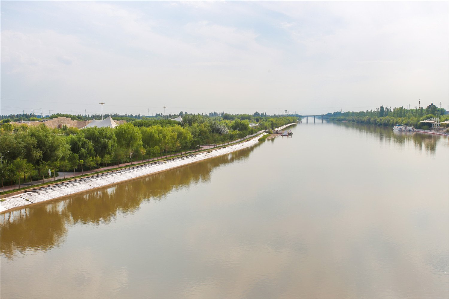
Project parameters:
- Design velocity (V): 5.0 m/s
- Flow depth (y): 2.8 m
- Channel slope (S): 0.002 m/m
- Side slope: 1:2.5 (V:H), β = 21.8°
- Concrete unit weight (ρ_c): 2,350 kg/m³
- Target safety factor: 1.3
- Available block sizes: 200 mm, 250 mm, 300 mm standard ACM
Step 1: Froude number check
Fr = 5.0 / √(9.81 × 2.8) = 5.0 / 5.24 = 0.95
Subcritical, but near-critical. Apply SF ≥ 1.3 per the guidance in the preceding section.
Step 2: Isbash block thickness (flat bed, no SF)
D = V² / [C_s² × 2g × (S_s − 1)]
D = 25.0 / [0.7396 × 19.62 × 1.35]
D = 25.0 / 19.59 = 0.213 m (213 mm)
Step 3: Apply slope correction K_1
φ = 37° (cable-tied ACM on geotextile)
K_1 = √(1 − [sin²(21.8°) / sin²(37°)]) = √(1 − [0.1377 / 0.3624]) = √(1 − 0.380) = √0.620 = 0.787
Adjusted D for slope: D_slope = D / K_1 = 213 / 0.787 = 271 mm
Step 4: Apply safety factor
D_design = D_slope × SF² = 271 × (1.3)² = 271 × 1.69 = 458 mm
The 500 mm block section satisfies SF = 1.3 on a 1:2.5 slope at 5.0 m/s.
Step 5: Shields verification
Hydraulic radius (approximate wide channel): R ≈ y = 2.8 m
Manning’s n for ACM: 0.020
S_f from Manning’s: V = (1/n) × R^(2/3) × S_f^(1/2) → S_f = (V × n / R^(2/3))² = (5.0 × 0.020 / 2.835)² = (0.0353)² = 0.00125 m/m
τ_b = 1,000 × 9.81 × 2.8 × 0.00125 = 34.3 Pa
τ* = 34.3 / [(2,350 − 1,000) × 9.81 × 0.300] = 34.3 / (1,350 × 9.81 × 0.300) = 34.3 / 3,973 = 0.00863
This is well below τ*_cr = 0.040, confirming the 300 mm block satisfies Shields stability for the bed shear mechanism. The Isbash (slope-corrected) condition governs in this case — 500 mm required.
Design recommendation: Specify 500 mm block ACM with ρ_c ≥ 2,350 kg/m³ on the 1:2.5 slope sections. 300 mm blocks are adequate for the flat apron zones where slope correction does not apply.
Sensitivity Table: Velocity × Block Thickness × Safety Factor
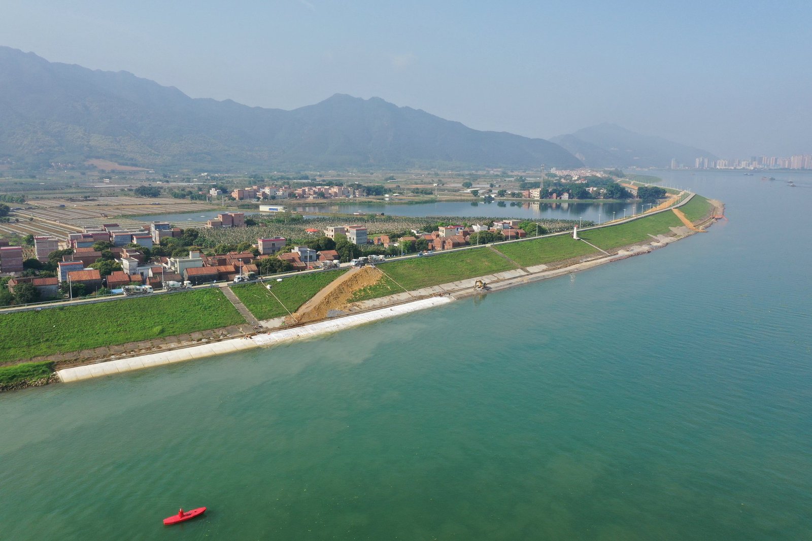
The table below provides computed safety factors for standard ACM block thicknesses across the 2.0–6.0 m/s velocity range. Assumptions: C_s = 0.86, ρ_c = 2,350 kg/m³, flat bed (no slope correction), standard Isbash equation.
| Velocity (m/s) | 100 mm Block SF | 150 mm Block SF | 200 mm Block SF | 250 mm Block SF | 300 mm Block SF | 400 mm Block SF |
|---|---|---|---|---|---|---|
| 2.0 | 1.74 | 2.13 | 2.46 | 2.75 | 3.01 | 3.48 |
| 2.5 | 1.39 | 1.70 | 1.97 | 2.20 | 2.41 | 2.78 |
| 3.0 | 1.16 | 1.42 | 1.64 | 1.83 | 2.01 | 2.32 |
| 3.5 | 0.99 | 1.22 | 1.41 | 1.57 | 1.72 | 1.99 |
| 4.0 | 0.87 | 1.06 | 1.23 | 1.37 | 1.50 | 1.74 |
| 4.5 | 0.77 | 0.94 | 1.09 | 1.22 | 1.34 | 1.54 |
| 5.0 | 0.69 | 0.85 | 0.98 | 1.10 | 1.20 | 1.39 |
| 5.5 | 0.63 | 0.77 | 0.89 | 1.00 | 1.09 | 1.26 |
| 6.0 | 0.58 | 0.71 | 0.82 | 0.91 | 1.00 | 1.16 |
Reading the table: Cells below SF = 1.00 (shaded conceptually) represent unstable configurations. Cells at 1.00–1.25 are marginally stable — acceptable only for temporary or low-consequence applications. Standard engineering practice targets SF ≥ 1.25 for permanent works, SF ≥ 1.5 for critical infrastructure (bridge abutments, culvert aprons, dam toe protection).
Key observations:
- At 5.0 m/s, no block thinner than 250 mm achieves SF ≥ 1.0 on a flat bed — and slope corrections will push the minimum toward 400–500 mm.
- The 300 mm block hits SF = 1.0 exactly at 6.0 m/s, which is why it represents a practical upper limit for standard ACM without high-density concrete.
- Upgrading concrete density from 2,350 to 2,500 kg/m³ adds approximately 0.08–0.12 to the SF across all velocity ranges — worth specifying when designs are borderline.
For the full worked methodology behind how to calculate concrete mattress thickness including slope correction charts and drainage layer design, additional resources are available.
Key Design Standards: CIRIA C683, EM 1110-2-1601
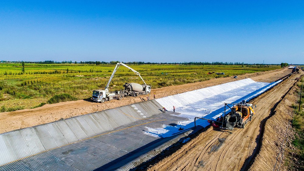
ACM hydraulic design doesn’t exist in a standards vacuum. Two documents dominate professional practice, and knowing where they agree — and diverge — matters for producing a defensible design.
CIRIA C683 (The Rock Manual, 2007):
Primarily oriented toward rock armour and rip-rap, C683 Section 5.2 provides the most comprehensive treatment of the Shields parameter and turbulence correction factors available in a single reference. Its turbulence intensity guidance (distinguishing between normal rivers, tidal channels, and near-structure zones) is directly applicable to ACM design even though the manual predates widespread ACM use. The C683 turbulence factor K_t = 1 + 3σ_u/U is the standard industry approach for amplifying design shear stress in disturbed flow.
EM 1110-2-1601 (USACE, 2009 revision):
The US Army Corps of Engineers manual is the most widely referenced document for ACM stability in North America and has significant influence on international project specifications. Chapter 3 covers flexible revetment design using the Isbash framework, with specific guidance on C_s values for different block configurations. Notably, EM 1110-2-1601 recommends C_s = 0.86 for blocks flush with the bed and C_s = 1.20 for exposed blocks — the distinction between a well-seated ACM panel and a poorly bedded one has a material effect on design velocity.
HEC-11 (FHWA, Design of Riprap Revetment):
While primarily a riprap document, HEC-11’s velocity-to-particle-size curves are routinely used as a first-check cross-reference against Isbash calculations. Agreement within 15% between HEC-11 and Isbash outputs is generally accepted as confirmation of the design approach.
HEC-23 (FHWA, Bridge Scour and Stream Instability Countermeasures):
For ACM around bridge piers and abutments, HEC-23 provides pier scour amplification factors and minimum extent-of-coverage requirements. The V_pier = K_1 × K_2 × V multiplier for pier geometry can increase the effective design velocity by 30–60% over the approach channel velocity — a calculation step that frequently gets skipped in preliminary design.
Practical standard application checklist:
| Design Location | Primary Standard | Secondary Check | Key Parameter |
|---|---|---|---|
| Straight channel reach | EM 1110-2-1601 | CIRIA C683 (turbulence) | C_s, τ*_cr |
| Channel bend | EM 1110-2-1601 + bend factor | HEC-11 | Velocity multiplier 1.5–2.0 |
| Bridge pier/abutment | HEC-23 | EM 1110-2-1601 | Pier scour multiplier K_1K_2 |
| Culvert apron | HEC-14 | EM 1110-2-1601 | Hydraulic jump zone sizing |
| Coastal/tidal | CIRIA C683 | DNV-GL RP-F109 | Wave orbital velocity |
| Steep slope (Fr > 1) | EM 1110-2-1601 App. C | CIRIA C683 | Roll wave factor |
Pre-Design Verification Checklist for ACM Stability Analysis
Before finalising any ACM specification, run through this checklist. It’s a condensed version of the workflow an experienced revetment engineer would use on a serious project:
Hydraulic inputs:
- [ ] Design velocity confirmed from hydraulic model (1D HEC-RAS minimum; 2D preferred near structures)
- [ ] Froude number computed — identify sub/super/critical flow zones
- [ ] Hydraulic radius calculated at design discharge
- [ ] Friction slope S_f computed independently of assumed Manning’s n
Stability calculation:
- [ ] Isbash equation run with project-specific ρ_c (not default 2,400 kg/m³ unless confirmed)
- [ ] C_s value selected based on block configuration (embedded vs. exposed)
- [ ] Slope correction K_1 applied for any bank steeper than 1:10
- [ ] Turbulence factor K_t applied in near-structure zones
- [ ] Shields parameter verified as secondary check
- [ ] Safety factor ≥ 1.25 for permanent works, ≥ 1.5 for critical infrastructure
Near-structure zones:
- [ ] HEC-23 pier scour amplification applied at bridge foundations
- [ ] Hydraulic jump zone identified and separately sized
- [ ] Roll wave factor applied if slope > 1:20
Filter design:
- [ ] Geotextile D_15/D_85 filter compatibility confirmed
- [ ] Permittivity ≥ 0.5 s⁻¹ for dynamic flow conditions
- [ ] Overlap and seaming specification matched to installation method
Block specifications:
- [ ] Block thickness confirmed from sensitivity table for target SF
- [ ] Concrete unit weight specified with minimum (not nominal) value
- [ ] Cable or rope tie specification reviewed for installation tension limits
- [ ] Open area percentage confirmed against hydraulic permeability requirement
ACM designs that fail in the field almost always skipped two or three items from a checklist like this. Slope correction is the most common omission.
Need a concrete mattress solution for your project?
HydroBase provides end-to-end concrete mattress engineering & installation services — from hydraulic design and factory-direct ACM supply to on-site supervision and post-project inspection. Trusted by civil engineers in 50+ countries.