
Flood Defense with Articulated Concrete Mattress: Design Guide for Levee and Floodwall Scour and Overtopping Protection
Quick Answer: Levee scour protection with concrete mattress addresses two distinct failure scenarios: toe scour under flood currents (design velocity 3–5 m/s using the Isbash equation) and wave overtopping on the landward face (design wave height 0.5–2 m using EurOtop methods). USACE EM 1110-2-1601 and FEMA P-259 provide governing design guidance for articulated concrete mattress revetment systems.
Flood defense levees fail in predictable ways — and articulated concrete mattress (ACM) is engineered to stop both of them. With nearly two decades spent specifying levee revetment systems across Southeast Asian river systems and reviewing USACE-compliant flood defense designs, I’ve seen firsthand why levee scour protection concrete mattress installations consistently outperform riprap and poured concrete alternatives when properly designed.
This guide walks through the two governing failure modes, the design equations you’ll actually use in practice, the regulatory standards you need to reference, and how ACM performs on earthen levees across monsoon-driven river systems. Engineers responsible for flood defense structures on major rivers — from the Mississippi to the Mekong — will find a working design framework here.
Table of Contents
1. Two Failure Modes for Levees
2. Toe Scour Design (Isbash)
3. Overtopping Design (EurOtop)
4. USACE and FEMA Design Standards
5. ACM on Earthen Levees in Southeast Asia
6. Typical Section Detail
7. Frequently Asked Questions
Two Failure Modes for Levees
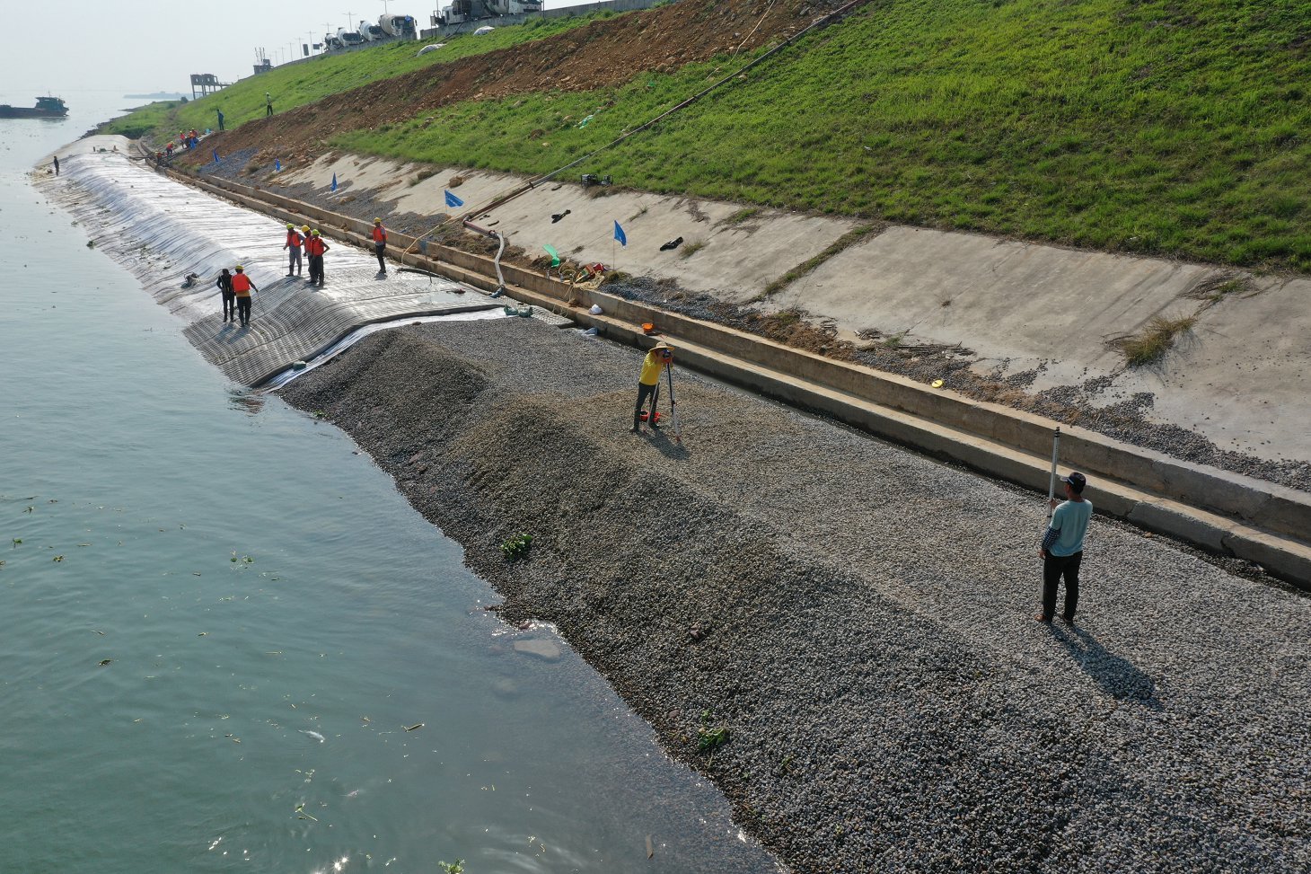
Every levee engineer should have two failure scenarios permanently in mind during the design phase. Get either one wrong and the entire embankment becomes a liability.
Failure Mode 1: Toe Scour
Current-driven scour at the levee toe is the more common initiator of catastrophic levee breach. During high-flow events, velocities at the toe regularly exceed 3.0 m/s — enough to mobilize fine to medium sands rapidly. Once the toe loses support, the slope face begins to slide. What starts as surface erosion progresses to mass failure in hours, sometimes minutes.
The mechanism is deceptively simple. High-velocity flow separates from the levee face near the toe, creating turbulent eddies that excavate material beneath the revetment’s lower edge. If the revetment doesn’t extend deep enough below the anticipated scour surface, it loses its toe anchorage and rolls up like a carpet.
Failure Mode 2: Wave Overtopping
Overtopping damage occurs when wave action during storm surge or wind-driven flood events sends water sheets across the levee crest and down the landward face. The landward slope is typically unprotected or lightly vegetated — fine for normal seepage conditions, catastrophic when overtopping discharge rates exceed the erosional resistance of bare earthen fill.
Even modest mean overtopping discharges — as low as 1–5 l/s/m for unprotected grass slopes — can initiate landward slope failure within minutes. The failure path then progresses to full breach as the crest erodes away.
Both failure modes require separate design calculations, separate revetment geometries, and sometimes different ACM specifications for the same levee cross-section.
Toe Scour Design (Isbash)
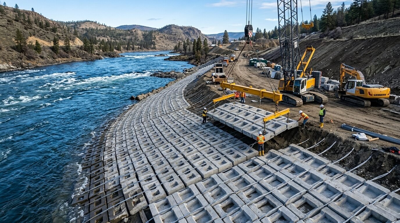
The Isbash equation remains the practical workhorse for sizing concrete armor at levee toes. It directly relates the required block thickness to the design velocity, making it straightforward to apply in preliminary design and easy to verify during detailed calculations.
The Isbash Equation:
$$d_{50} = \frac{V^2}{C^2 \cdot 2g \cdot (S_s – 1)}$$
Where:
– d₅₀ = equivalent spherical diameter of armor unit (m)
– V = depth-averaged design velocity (m/s)
– C = Isbash stability coefficient (0.86 for embedded, 1.20 for exposed placement)
– g = 9.81 m/s²
– Sₛ = specific gravity of concrete (typically 2.35–2.40 for standard C30 mix)
Worked Design Example — Levee Toe Protection
Assume a design velocity of 4.2 m/s (post-flood survey data), exposed placement on a 1V:2H slope, and a concrete specific gravity of 2.38:
d₅₀ = (4.2²) / (1.20² × 2 × 9.81 × (2.38 − 1))
d₅₀ = 17.64 / (1.44 × 19.62 × 1.38)
d₅₀ = 17.64 / 39.04
d₅₀ = 0.452 m
That equates to an equivalent block thickness of roughly 450 mm. For a standard cable-tied ACM panel with 500×350×150 mm blocks at 2.35 t/m³, you’re slightly under the requirement. Stepping up to 600×400×200 mm blocks at a unit weight of approximately 113 kg/block resolves the deficit and provides a practical safety margin.
Design Velocity Selection
Don’t use mean channel velocity as your design input — use the toe velocity, which typically runs 1.2–1.4× the cross-section mean during peak flood. Hydraulic modelling (HEC-RAS or equivalent 2D model) is the reliable method for levee toe velocity extraction. For screening-level estimates, a velocity amplification factor of 1.25 applied to measured mean velocity is a reasonable conservative starting point.
Scour Depth and Toe Extension
The ACM panel must extend below the anticipated scoured bed. For cohesionless sands in major river systems, scour depth at levee toes under 100-year flood conditions commonly reaches 2–4 m. The revetment’s toe extension should match or exceed this depth. A buried toe trench — filled with ACM rolled into a flexible toe — is standard practice on major Southeast Asian rivers.
For a deeper treatment of how scour propagates beneath revetment systems, the concrete mattress scour protection mechanism and design principles resource covers substrate interaction in detail.
Overtopping Design (EurOtop)
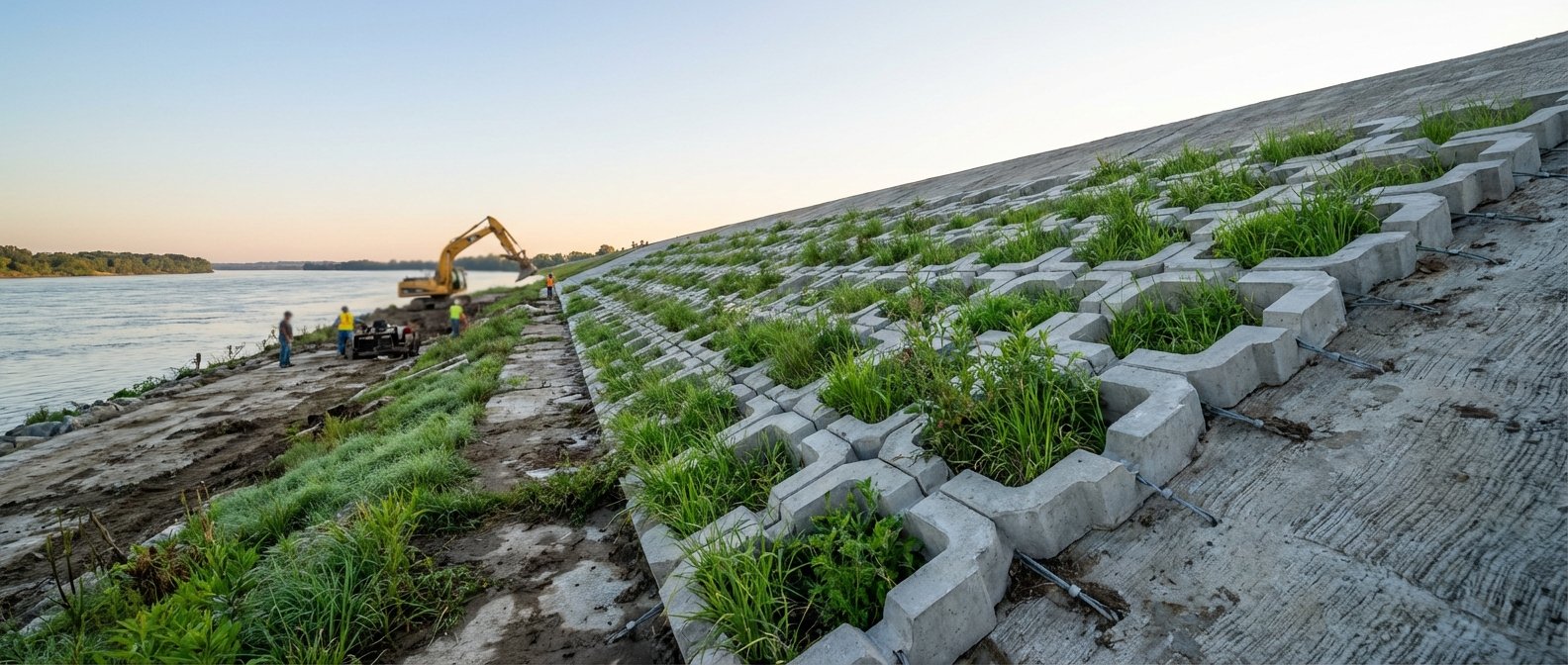
Wave overtopping design on levees uses the EurOtop manual methodology — the international standard for quantifying mean overtopping discharge across coastal and flood defense structures.
Mean Overtopping Discharge (EurOtop Empirical Form):
$$q = 0.047 \sqrt{g \cdot H_{m0}^3} \cdot \exp\left(-2.35 \cdot \frac{R_c}{H_{m0} \cdot \xi_m}\right)$$
Where:
– q = mean overtopping discharge per unit width (m³/s/m)
– Hm0 = significant wave height at structure toe (m)
– Rc = crest freeboard (m)
– ξm = Iribarren number (breaker parameter)
– g = 9.81 m/s²
Permissible Discharge Thresholds for Revetment Design
| Slope Condition | Permissible Mean Discharge |
|---|---|
| Unprotected bare earthen fill | < 0.1 l/s/m |
| Well-maintained grass slope | 1–5 l/s/m |
| ACM-protected slope (open block) | Up to 50 l/s/m |
| ACM-protected slope (closed block, grouted) | Up to 200 l/s/m |
When your hydraulic model returns overtopping discharges above 5 l/s/m for the design storm, you’re outside the reliable performance range of grass-only protection. That’s the threshold where ACM on the landward slope becomes a non-negotiable specification.
Wave Height Input — Southeast Asian Floodplain Context
Wind-wave generation across large floodplain inundation zones during typhoon or monsoon events can produce significant wave heights of 0.5–1.5 m over fetch lengths of 2–10 km. On wide-floodplain rivers and coastal flood defense systems, Hm0 = 1.0–2.0 m at the levee face is a realistic design range. These wave heights generate overtopping discharges far above the grass-protection threshold on typical 1V:3H landward slopes.
USACE and FEMA Design Standards
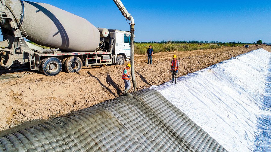
Two governing documents shape ACM specification on US flood defense projects — and their influence extends to internationally funded projects through World Bank and ADB infrastructure standards.
USACE EM 1110-2-1601: Hydraulic Design of Flood Control Channels
This Engineering Manual remains the authoritative reference for riprap and concrete revetment sizing on USACE-regulated channels and levees. Chapter 3 covers velocity-based sizing methodology directly applicable to ACM block design. Key parameters include:
– Side slope correction factor (Cs) for slopes steeper than 1V:2H
– Safety factors of 1.1–1.5 applied to computed d₅₀ depending on consequence class
– Geotextile filter layer specifications (AOS ≤ 0.6 mm for fine sand substrates)
– Minimum panel overlap of 0.3 m at transverse joints
For levee toe protection specifically, EM 1110-2-1601 recommends extending armor to a depth of 1.5× the predicted scour depth — a more conservative requirement than the Isbash equation alone implies.
FEMA P-259: Engineering Principles and Practices for Retrofitting Flood-Prone Residential Structures
FEMA P-259 becomes relevant for levee overtopping retrofit projects. It provides guidance on acceptable overtopping performance for existing earthen levees that cannot be raised, where armoring the crest and landward face with ACM is the remediation strategy. The document establishes that properly anchored ACM can maintain structural integrity through sustained overtopping events up to the design discharge.
FEMA Hazard Mitigation Grant Programs (HMGP)
Many ACM levee protection projects in the US are partially funded through FEMA HMGP. Eligibility requires documentation that the revetment system prevents repetitive flood loss — which ACM systems achieve by extending levee service life from a typical 20–30 years (unprotected earthen) to 50+ years with proper maintenance.
ACM on Earthen Levees in Southeast Asia
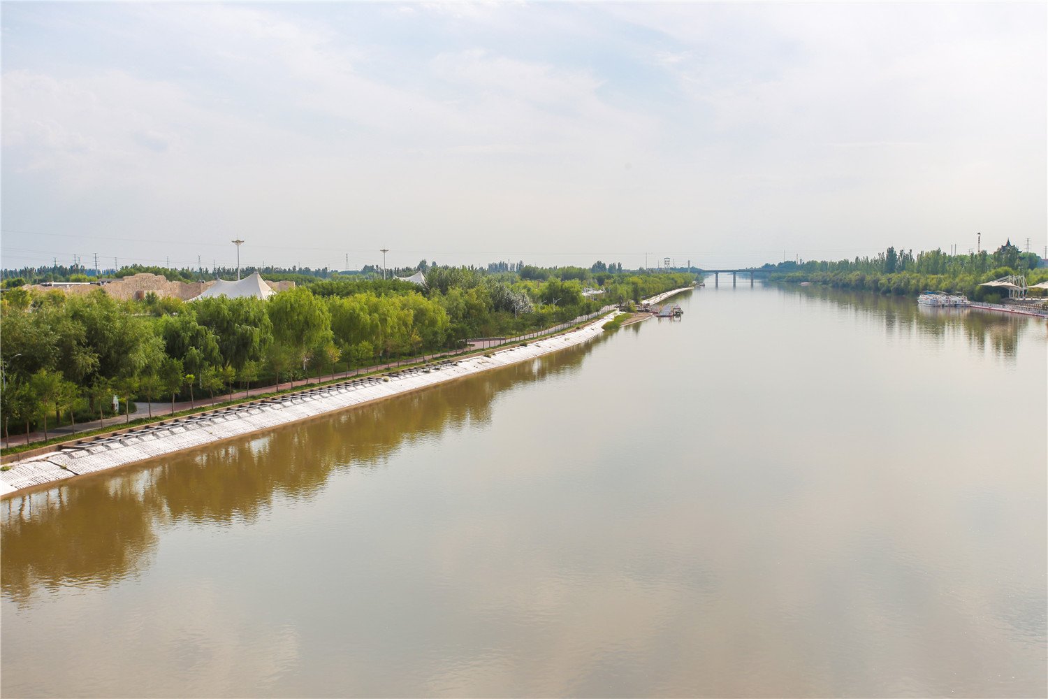
Southeast Asia’s flood defense infrastructure presents conditions that genuinely test revetment systems. The Mekong, Irrawaddy, Chao Phraya, and Red River systems all deliver annual flood peaks that would be considered extreme events on most temperate-zone rivers. Monsoon flood velocities of 3.5–5.0 m/s at levee toes are routine, not exceptional.
Why ACM Dominates Earthen Levee Revetment Here
Riprap sourcing is the fundamental constraint. Quality quarried stone meeting USACE gradation requirements simply isn’t available cost-effectively across most of the Mekong Delta, the Irrawaddy floodplain, or the low-lying coastal zones of Vietnam and Bangladesh. ACM manufactured at regional precast facilities provides consistent quality control that quarried rock cannot match in these geographies.
Vegetation maintenance — the alternative for slope protection on lower-discharge situations — fails on high-monsoon-velocity rivers where flow duration exceeds 60 days above bankfull. Grass root systems don’t survive that kind of sustained submergence and shear stress.
Practical Installation Conditions
On major Southeast Asian river levees, ACM panels are typically:
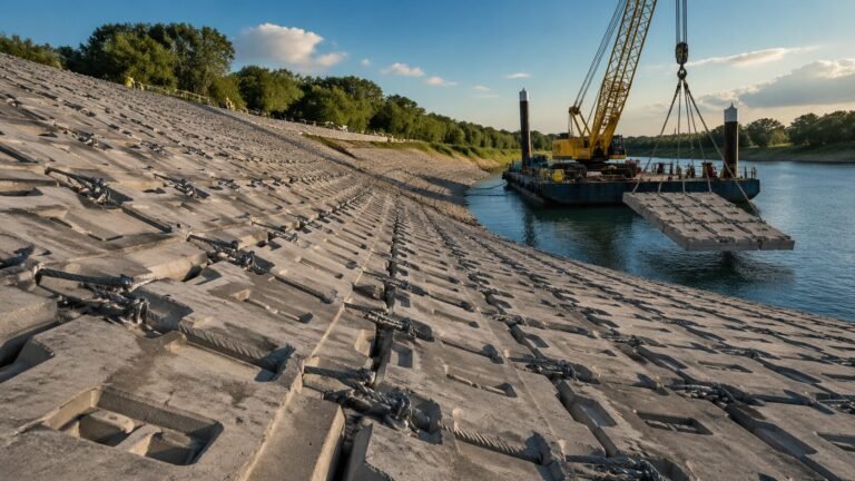
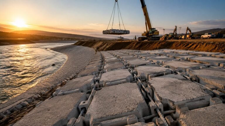
– Crane-laid from barge during low-season drawdown
– Panel size: 3.0 × 6.0 m to 4.0 × 8.0 m as standard lifting units
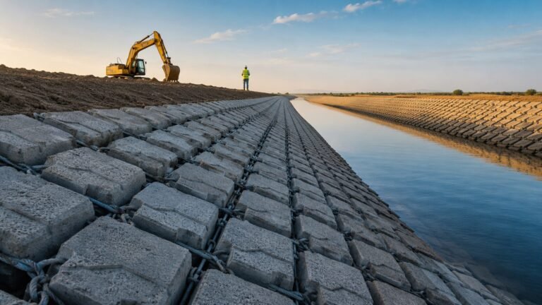
– Block specification: 300×200×100 mm (light duty, V ≤ 3.5 m/s) to 500×350×150 mm (heavy duty, V ≤ 5.5 m/s)
– Stainless steel cable ties (AISI 316) for saline tidal influence zones; galvanized for freshwater levees
– Geotextile filter layer: 200 g/m² non-woven, AOS 0.075–0.212 mm for silt/fine sand substrates
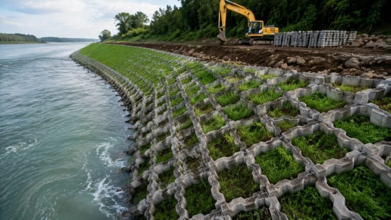
The open-block pattern — typically 30–40% open area — is preferred on vegetated levee slopes where root establishment through the mattress openings provides secondary erosion resistance and reduces peak overtopping discharge coefficients by 10–15%.
For engineers designing full slope protection systems beyond the levee toe, the slope protection concrete mattress design guide for embankments and levees covers gradient and velocity combinations across typical levee geometries.
Typical Section Detail
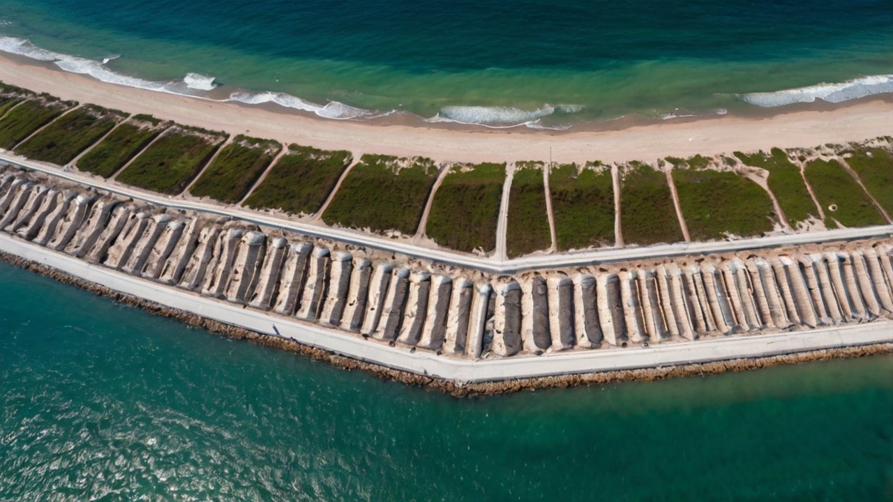
A properly detailed ACM levee section integrates four distinct protection zones. Each has a defined function and a specific ACM specification.
Zone 1: Waterward Slope Revetment
– Extends from crest elevation to 0.5 m below low-water level
– Block size: matched to design toe velocity via Isbash
– Open-block pattern with geotextile underlayer
– Cable spacing: 300–400 mm maximum
Zone 2: Toe Trench (Critical Detail)
– Trench depth: 1.5–2.0× predicted scour depth below bed level
– ACM rolled into trench in a flexible toe configuration
– Allows passive settlement into scour hole without unraveling
– Trench backfilled with granular material after ACM placement
Zone 3: Crest Protection
– ACM across full crest width (minimum 3.0 m) where overtopping is design scenario
– Closed-block pattern recommended for crest: eliminates surface turbulence
– Block anchors at upstream and downstream crest edges
Zone 4: Landward Slope Protection
– ACM from crest to 1.0 m below levee base elevation on landward side
– Open-block pattern to facilitate drainage after overtopping event
– Anchor trench at base with 0.5 m toe embedment
B2B Specification Checklist: ACM Levee Protection
| Parameter | Design Input | Specification Output |
|---|---|---|
| Design velocity (toe) | 3.0–5.5 m/s | Block thickness 100–200 mm |
| Wave height (Hm0) | 0.5–2.0 m | Open vs. closed block selection |
| Slope gradient (waterward) | 1V:2H–1V:3H | Side slope stability check required |
| Substrate type | Sand / silt / clay | AOS filter selection |
| Scour depth (predicted) | 1.5–4.0 m | Toe trench depth |
| Panel lifting weight | Per crane capacity | Panel size 3×6 m to 4×8 m |
| Saline exposure | Yes / No | AISI 316 vs. galvanized cable |
| Overtopping design discharge | l/s/m | Crest + landward slope ACM |
For procurement teams comparing specifications between suppliers, the articulated concrete mattress procurement guide for international buyers provides a detailed quality checklist covering cable pull-out strength, concrete compressive strength testing, and panel dimensional tolerances.
HydroBase manufactures ACM panels specifically rated for flood defense levee applications, with block sizes from 300×200×100 mm through 600×400×200 mm and velocity ratings validated to 6.0 m/s. Their articulated concrete mattress product range includes both open and closed block configurations with geotextile filter layers factory-bonded to the underside — a detail that eliminates filter displacement risk during underwater installation. For projects in Southeast Asia particularly, HydroBase’s regional manufacturing and barge-delivery capability has made them a practical supplier choice on ADB and World Bank-funded levee upgrading programs. As our lead installation engineer always says, “You can feel when the cable tension is right.”
Frequently Asked Questions
Q: What block thickness should I specify for levee toe scour protection with an articulated concrete mattress?
Block thickness is determined by the Isbash equation using the design toe velocity. For velocities of 3.0–3.5 m/s, a 100 mm block thickness is typically sufficient. Velocities of 4.0–5.0 m/s require 150–200 mm blocks. Always apply a minimum safety factor of 1.15 per USACE EM 1110-2-1601 and verify that the geotextile filter AOS matches your substrate gradation.
Q: What is the difference between toe scour protection and overtopping protection for levees?
Toe scour protection resists current-driven erosion at the base of the waterward levee face using velocity-rated ACM blocks sized by the Isbash equation. Overtopping protection addresses wave-driven water sheets flowing down the landward face, sized using EurOtop discharge thresholds. Both zones require separate hydraulic calculations and may need different block patterns — open-block on vegetated slopes, closed-block on crest and high-discharge zones.
Q: How far below the bed level should the ACM toe trench extend on a river levee?
Extend the toe trench to a minimum of 1.5× the predicted scour depth below the existing bed level. On major alluvial rivers in Southeast Asia, this typically means 2.5–4.0 m below low-water bed elevation. The ACM panel is rolled into the trench in a flexible configuration, allowing it to settle passively into any scour hole that develops without unraveling from the bottom up.
Q: What is the minimum supply quantity and typical lead time for ACM levee protection panels?
Minimum order quantities for ACM panels from specialist manufacturers typically start at 500–1,000 m² for levee projects, with standard lead times of 6–10 weeks ex-factory for project-specific block sizes. Larger levee programs (>10,000 m²) commonly negotiate staged delivery schedules aligned with barge installation windows during dry-season drawdown. Request factory test certificates for compressive strength (≥30 MPa) and cable pull-out force (≥2.5 kN) with each supply batch.
Ready to Specify ACM for Your Flood Defense Project?
If you’re designing a levee revetment system and need manufacturer data sheets, velocity rating certification, or geotextile filter specifications to complete your design package, the articulated concrete mattress technical specifications and product range at concretemattress.com includes downloadable datasheets, block dimension tables, and project application references for flood defense.
For design-phase queries — block size selection, cable specification, or geotextile AOS matching for your substrate — reach out with your hydraulic design inputs and get a specification recommendation within 48 hours.
Conclusion
Flood defense levees fail at the toe and at the crest. Articulated concrete mattress addresses both failure modes within a single material system — a flexibility that riprap and poured concrete cannot match on irregular or settling earthen embankments.
The design framework is well-established: Isbash equation for toe velocity sizing, EurOtop for overtopping discharge thresholds, USACE EM 1110-2-1601 for safety factors and filter design. What distinguishes successful levee ACM projects from failures is the section detail — specifically the toe trench depth, the filter AOS selection for fine substrate soils, and the transition between waterward and landward slope specifications.
Southeast Asia’s monsoon-driven river systems have made ACM the default levee revetment solution where rock is scarce and flood velocities are severe. As climate loading increases design return periods globally and more levees reach the end of their design life, demand for properly engineered ACM flood defense systems will continue to grow. Engineers who understand both failure modes and the corresponding design equations will be well-positioned to specify systems that genuinely perform when the flood arrives.
Need a concrete mattress solution for your project?
HydroBase provides end-to-end concrete mattress engineering & installation services — from hydraulic design and factory-direct ACM supply to on-site supervision and post-project inspection. Trusted by civil engineers in 50+ countries.