Scour Protection at Offshore Wind Farm Foundations: How Articulated Concrete Mattress Is Used
Quick Answer: Monopile foundations at offshore wind farms are highly susceptible to scour due to concentrated tidal and wave-driven currents around the pile. Articulated concrete mattress is deployed as a pre-installed scour apron extending 2–3 pile diameters from the pile face, or post-installed after initial scour detection. Design follows DNV-ST-0126 guidance, with a crushed rock or non-woven geotextile filter layer beneath the mattress.
—
Offshore wind foundation scour protection has become one of the most technically demanding challenges in the renewable energy sector. As someone who has spent nearly two decades watching this market evolve — from early North Sea deployments to today’s multi-gigawatt projects off the coasts of Taiwan, the Netherlands, and the UK — I can say with confidence that getting the scour protection design right from day one is what separates a 25-year asset from a costly remediation nightmare. This article draws on established design standards and practical field experience to walk project developers, foundation engineers, and O&M teams through exactly how articulated concrete mattress is applied in this environment.
—
Table of Contents
1. Why Offshore Wind Foundations Scour
2. DNV-ST-0126 Design Guidance
3. ACM Scour Apron Design
4. Pre-Installation vs Post-Installation
5. Cable Crossing Protection with ACM
6. Filter Layer Requirements
7. Frequently Asked Questions
—
Why Offshore Wind Foundations Scour
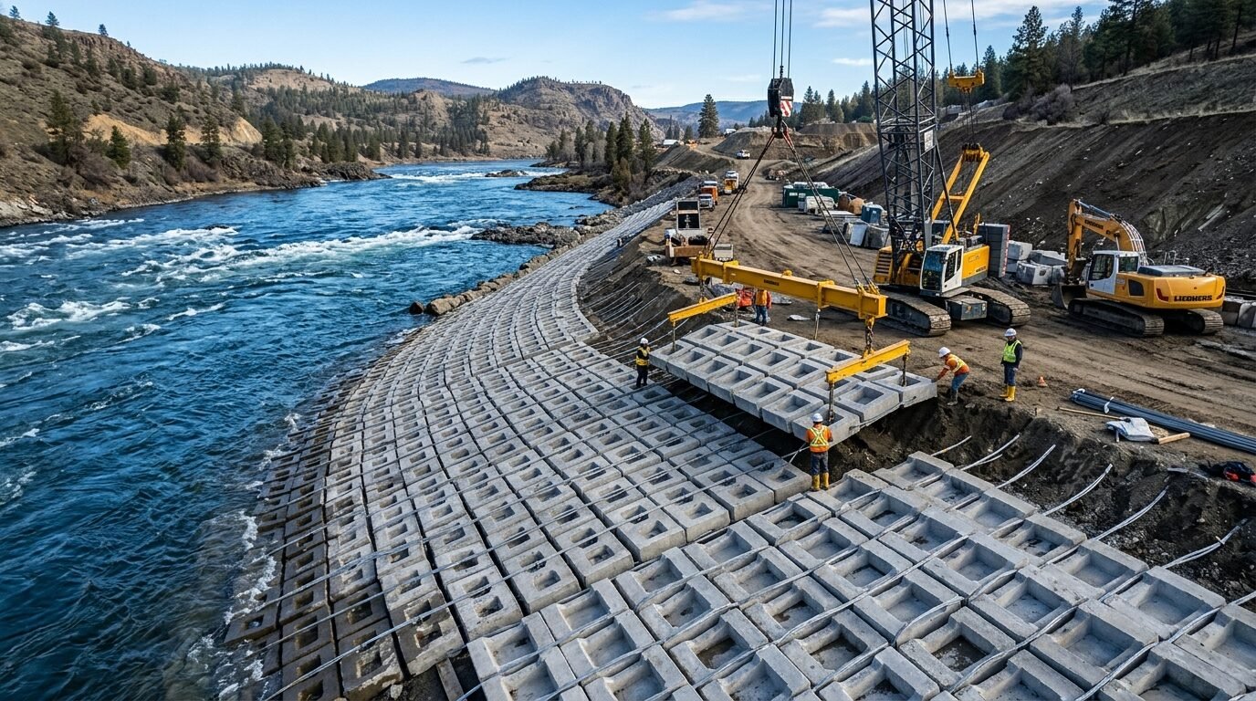
Scour around offshore structures is driven by the interaction between flowing water and the seabed, but a monopile foundation creates a particularly aggressive hydrodynamic environment. When tidal currents or combined wave-current flows encounter a large-diameter cylindrical pile — typical monopile diameters now range from 6 m to 11 m for current-generation turbines — the flow separates and generates a horseshoe vortex at the base of the pile. That vortex system spirals around the pile face, shedding wake vortices downstream, and the combined effect can mobilise seabed sediment at rates far exceeding the ambient transport capacity.
The physics here aren’t subtle. Studies on large-diameter monopile scour consistently show equilibrium scour depths reaching 1.0 to 2.5 times the pile diameter (D) under steady current-only conditions, and up to 1.3D under combined wave-current loading. For a 9-metre monopile, you’re potentially looking at 9–23 metres of scour depth at equilibrium — a figure that would fundamentally alter the lateral load-deflection response of the foundation and could invalidate the original geotechnical design.
What makes offshore wind sites particularly problematic is the combination of factors that drive scour. Many high-quality wind resource areas sit in relatively shallow water (15–35 m) with sandy or silty seabeds — exactly the conditions that produce rapid scour development. Tidal velocities at commercially attractive sites frequently exceed 0.8 m/s at mean spring tide, and during storm events, combined wave-current velocities at the seabed can push well above 1.5 m/s.
It’s worth noting that scour doesn’t just threaten the structural integrity of the foundation. Cables connecting the turbines to the offshore substation often run within the scour influence zone of multiple monopiles. When scour proceeds unchecked, those cables become suspended, exposed to hydrodynamic loading and impact damage, and the consequences cascade quickly through the whole array.
Understanding the scour mechanism is fundamental to designing an effective protection system. Unlike riverine or bridge pier scour — where you’re primarily dealing with unidirectional flow — offshore monopile scour occurs under oscillatory wave loading combined with a time-varying tidal current vector that rotates through the full compass over each tidal cycle. That omnidirectional loading pattern is why scour protection systems for offshore wind foundations must achieve full 360° coverage around the pile.
If you’re familiar with how the same principles apply in river environments, the detailed analysis in how articulated concrete mattresses protect riverbeds from scour: mechanism and design principles provides a useful comparative baseline for understanding how flow-induced bed shear stress drives sediment mobility.
—
DNV-ST-0126 Design Guidance
DNV-ST-0126 is the primary design standard governing support structure design for offshore wind turbines, and it contains specific provisions for scour and scour protection that every foundation engineer needs to understand before specifying a protection system.
The standard takes a risk-based approach. It requires that designers either demonstrate the foundation design is inherently robust against worst-case scour depths (the “scour-allowed” approach) or that an effective protection system is installed and maintained throughout the design life (the “scour-protected” approach). In practice, the majority of projects pursue the protected approach, because designing a monopile to tolerate 1.5D of scour substantially increases steel tonnage and fabrication cost.
Key design parameters that DNV-ST-0126 requires engineers to establish include:
| Parameter | Typical Range (Current Generation) |
|---|---|
| Monopile diameter | 6.0 – 11.0 m |
| Equilibrium scour depth (current only) | 1.0 – 2.5 × D |
| Design current velocity (100-year return) | 1.2 – 2.4 m/s |
| Scour protection apron radius | 2.0 – 3.0 × D |
| Minimum armour layer thickness | 0.5 – 1.5 m |
| Filter layer thickness (crushed rock) | 0.3 – 0.5 m |
| ACM block thickness (offshore rated) | 150 – 300 mm |
| Design service life | 25 – 30 years |
The standard requires scour protection to be designed for the 100-year return period current and wave conditions, not the operational mean. That’s a critical distinction — some early projects sized their protection systems against mean spring tide velocities and then found them displaced during the first major storm event.
DNV-ST-0126 also specifies that post-installation scour monitoring must be conducted, typically via multibeam bathymetric surveys at defined intervals — usually quarterly during the first two years, then annually thereafter. Any detected scour exceeding trigger levels defined in the Operations and Maintenance (O&M) plan must trigger a remediation assessment.
The standard doesn’t mandate a specific material for scour protection — rock armour, concrete mattress, and grouted systems all appear in approved designs — but it does require designers to demonstrate that the chosen system can withstand the design hydraulic loading, conform to the seabed geometry, and remain stable under the combined effects of wave, current, and marine growth loading over the full design life.
—
ACM Scour Apron Design
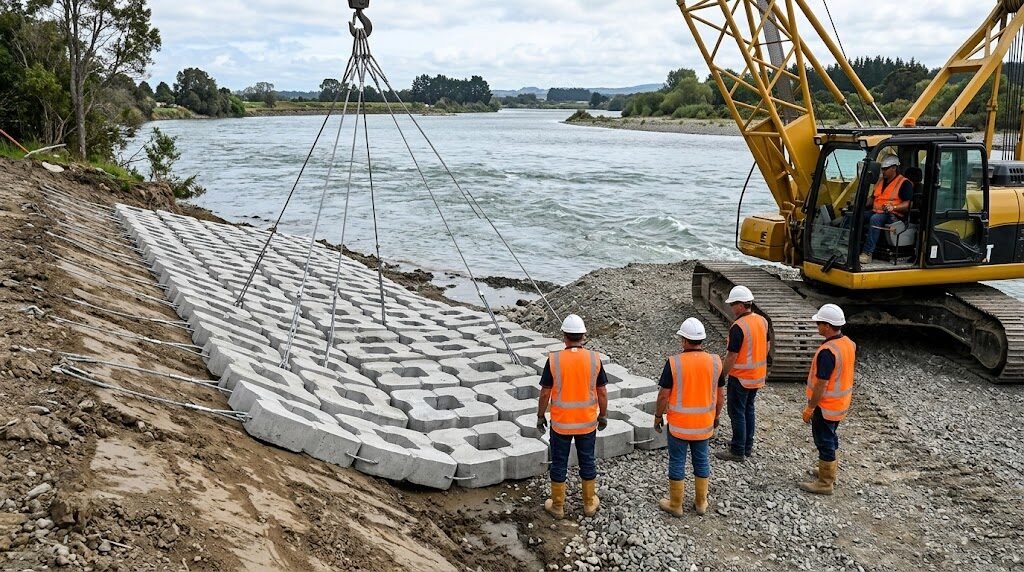
Designing the ACM scour apron for a monopile is an exercise in translating hydrodynamic loading into concrete block geometry and mattress configuration. The goal is a system that keeps the seabed stable within the protection zone while remaining flexible enough to conform to any initial settlement or scour that occurs during installation.
Apron Radius
Standard practice derived from physical model testing and field monitoring data places the apron edge at 2.0 to 3.0 pile diameters (D) from the pile centreline. For a 9 m diameter pile, that means a protection radius of 18–27 m. The 3D radius is typically specified for high-velocity sites or where the seabed is composed of fine-to-medium sand with a D50 in the range of 0.2–0.5 mm.
Block Size and Mattress Weight
Block dimensions for offshore scour apron applications typically run from 400×300×150 mm to 600×400×200 mm, depending on the design velocity. A 500×350×175 mm block in C35/45 concrete gives an individual block weight of approximately 75–90 kg — substantial enough to resist displacement under current velocities up to 4.5 m/s before drag and lift forces overcome submerged weight.
Mattress areal density (weight per square metre) for offshore scour apron work typically falls in the range of 180–350 kg/m². That’s meaningfully heavier than the 80–150 kg/m² systems commonly specified for riverbank or culvert outfall work, reflecting the more severe hydrodynamic loading offshore. For comparison, the design considerations for riverine applications are covered in this ACM vs Riprap vs Gabions engineering comparison guide for scour protection.
Cable Arrangement
Offshore mattress panels use marine-grade stainless steel cables (typically 316L, 10–14 mm diameter) or high-tenacity polypropylene rope with UV stabilisation. The cable grid centres are usually 300–400 mm in both directions. A key design detail: the cable terminations at panel edges need corrosion-resistant ferrules and swage fittings rated for the full tensile load of the cable — marine environments eat through substandard terminations within 3–5 years.
Overlap and Jointing
Adjacent mattress panels are typically overlapped by 0.3–0.5 m at panel edges, with jointing cables run through the end loops of adjacent panels to create a continuous surface. The overlap prevents sediment from being drawn out through the gap between panels under oscillatory wave loading — a failure mode that’s been observed on early-generation systems where panels were merely butted together.
Mattress Articulation
The defining characteristic of ACM for scour protection applications is its ability to conform to an uneven or settling seabed. Individual concrete blocks are free to rotate within the cable matrix, accommodating vertical displacement of ±150 mm without compromising structural integrity. That matters enormously offshore, where post-storm seabed surveys routinely reveal mound migration and settlement in the 50–200 mm range around the protection perimeter.
—
Pre-Installation vs Post-Installation
Whether to install scour protection before or after pile driving is one of the most practically significant decisions in offshore wind foundation engineering — and it’s an area where project teams continue to get burned by assumptions made too early in the design process.
Pre-Installation
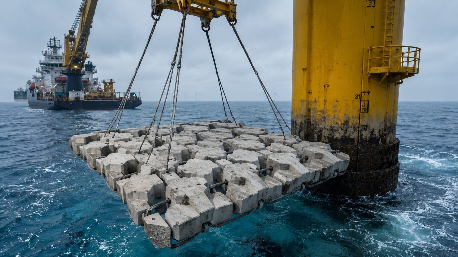
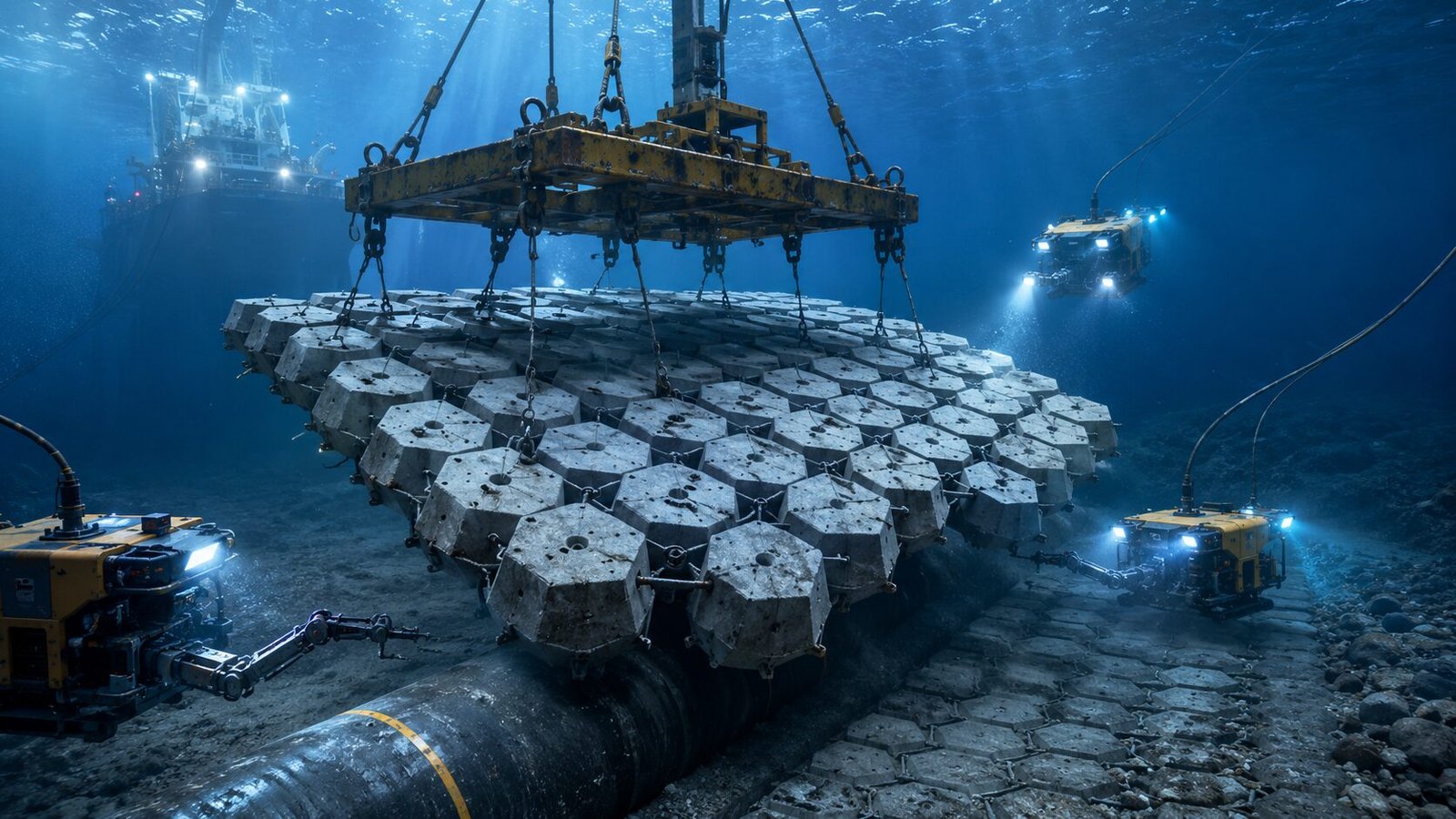
Pre-installation means placing the ACM scour apron on the seabed before the monopile is driven through the centre of it. Panels are fabricated with a central aperture matched to the pile diameter plus a practical clearance allowance (typically pile diameter + 0.5 m to 1.0 m). A crane barge or offshore installation vessel lowers panels sequentially from the outer edge toward the pile template, working from a pre-surveyed grid.
Advantages are significant. Pre-installation avoids the complication of working around an already-installed pile, the seabed surface is undisturbed, and the filter layer can be placed and levelled before the armour mattress goes down. The primary disadvantage is that pile driving can displace or damage a pre-installed system — hydraulic jetting and vibro-driving both generate lateral ground displacement that can shift the filter layer and disturb mattress alignment near the pile face.
Post-Installation
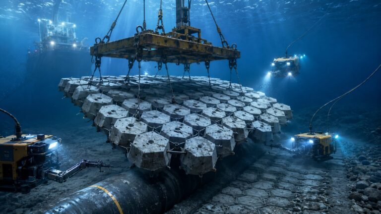
Post-installation is carried out after pile driving and typically after initial post-installation surveys have confirmed the scour pattern. Panels are designed with a C-shaped or semicircular cutout that allows them to be slid horizontally to engage the pile — or half-panels are installed from opposite sides and jointed beneath the pile. ROV-assisted installation is standard practice for final positioning.
The post-installation approach allows designers to confirm actual seabed conditions after driving, which often differ from pre-drive surveys. However, if there’s a delay between pile installation and scour protection placement — as frequently happens when vessels are shared across multiple turbine positions — initial scour can develop rapidly. On sandy sites with tidal velocities above 0.6 m/s, meaningful scour can develop within the first tidal cycle after pile installation.
Project teams need to decide early in the FEED phase which approach suits their installation sequence, vessel availability, and seabed conditions. Both approaches have strong track records when detailed installation procedures are followed rigorously.
—
Cable Crossing Protection with ACM
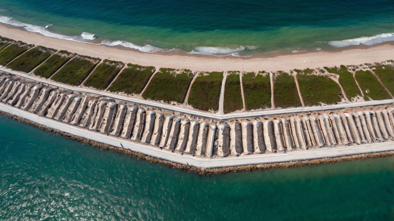
Inter-array cables at offshore wind farms face a distinct set of threats at the point where they cross or run close to scoured seabed zones. Cable protection with ACM addresses three specific scenarios:
Approach Trenches
Where cables enter the scour apron zone, the transition from buried cable to exposed cable must be managed carefully. ACM is used to armour the cable trench backfill over a distance of typically 10–20 m on either side of the scour apron perimeter, preventing the trench from being opened by scour-related seabed lowering.
Free-Span Prevention
Cable free-spans develop when scour propagates beneath a cable that’s already been buried or trenched. Once a free-span forms, the cable is subject to hydrodynamic drag and lift forces plus vortex-induced vibration (VIV) — a fatigue mechanism that can cause cable failure in surprisingly short timeframes. ACM placed as a spanning mattress across developing free-span zones provides an economic and rapidly deployable fix. Mattress thickness for this application typically runs 150–200 mm, with panels oriented parallel to the cable axis.
J-Tube and Hang-Off Protection
At the turbine foundation itself, cables transition from the seabed into the J-tube or I-tube mounted on the monopile structure. The seabed area immediately around the J-tube exit is prone to concentrated scour due to the current shadow effect of the pile. ACM is routinely specified here with reduced block sizes (300×200×100 mm) to achieve the close-fitting geometry required around the J-tube structure.
The same principles apply at near-shore cable landfall points, where cables transition from the marine environment to the onshore cable route. For a detailed look at scour protection challenges at the landfall and transitions to structures, the bridge scour protection: why articulated concrete mattress is the preferred solution for pier and abutment scour article explores the structural interface challenge in depth.
—
Filter Layer Requirements

No scour protection system functions correctly without a properly designed filter layer. This is arguably the most overlooked element in offshore wind scour protection design, and failures of the filter interface are responsible for a disproportionate share of scour protection system underperformance.
The filter layer serves two functions: it prevents the migration of fine seabed particles upward through the voids of the armour layer (a process called piping), and it provides a stable, level working surface for the ACM panels above.
Granular Filter
A crushed rock or graded gravel filter, typically D50 of 30–80 mm, placed at 300–500 mm thickness beneath the ACM, is the traditional approach for offshore scour protection. The grading must satisfy the Terzaghi filter criteria against the seabed material: D15(filter) / D85(base) ≤ 5, and D50(filter) / D50(base) ≤ 25. These ratios ensure the filter pores are small enough to retain base soil particles while remaining permeable enough to relieve excess pore pressure.
For typical North Sea or East Asian offshore sites with seabed D50 in the 0.2–0.5 mm range, a filter grading of D50 40–60 mm and D15 10–20 mm generally satisfies both criteria.
Geotextile Filter
Non-woven needle-punched geotextile offers an alternative to granular filter on sites where vessel time for rock placement is constrained. The geotextile must be rated for the offshore environment — UV resistance, hydrolysis resistance, and sufficient mass per unit area (typically ≥300 g/m²) to resist displacement during ACM panel installation. The apparent opening size (AOS or O90) must be selected against the seabed D50 to prevent piping.
Geotextile-only filter systems work well when the ACM is pre-installed, because the mattress is lowered directly onto a single-layer filter that’s already been surveyed and confirmed to be flat. For post-installation work where divers or ROVs are placing filter material around an existing pile, granular filter with a retention blanket is often easier to place accurately.
One practical note: on sites with significant biogenic carbonate content in the seabed sediment — common in tropical and subtropical offshore wind markets — standard filter design criteria derived from siliceous sediment data may need adjustment. Carbonate sands can be significantly finer and more compressible than their D50 suggests.
—
Pre-Installation Checklist: ACM Scour Apron for Monopile Foundations
This checklist consolidates the critical design and installation verification steps that engineering teams should complete before and during ACM deployment at offshore wind foundations.
| Stage | Check Item | Standard / Reference |
|---|---|---|
| Design | Confirm 100-year return current and wave velocity at seabed | DNV-ST-0126 Sec. 4 |
| Design | Calculate equilibrium scour depth (S/D ratio) | Physical model or SCOS method |
| Design | Verify apron radius ≥ 2.5D for sandy seabed | Site-specific risk assessment |
| Design | Select block size and mattress areal density | Velocity-weight stability curves |
| Design | Confirm filter layer grading satisfies Terzaghi criteria | D15(F)/D85(B) ≤ 5 |
| Design | Specify 316L stainless cable with corrosion-resistant terminations | ISO 3506, BS 6463 |
| Design | Panel aperture or cutout detail for pile clearance | Installation procedure |
| Procurement | Confirm mattress block strength ≥ C35/45 | EN 206 / BS 8500 |
| Procurement | Verify cable breaking load ≥ 3× design tensile force | Factory test certificates |
| Installation | Pre-lay multibeam survey of seabed within protection zone | ±50 mm accuracy |
| Installation | Verify filter layer level tolerance ±100 mm before ACM placement | Installation survey |
| Installation | Confirm panel overlap ≥ 0.3 m at all joints | As-built records |
| Installation | ROV or diver inspection of pile face clearance at all panels | Video record required |
| Post-Install | Bathymetric survey within 14 days of installation | Baseline for monitoring |
| O&M | Quarterly bathymetric surveys in Year 1 and Year 2 | DNV-ST-0126 monitoring |
—
HydroBase ACM for Offshore Wind Scour Protection
When project teams start evaluating concrete mattress suppliers for offshore wind applications, the qualification bar is genuinely high. Offshore work demands not just the right product, but verified production quality, traceability documentation, and the flexibility to accommodate project-specific panel geometries — the custom apertures, semicircular cutouts, and J-tube clearance details that differ from one project to the next.
HydroBase has supplied articulated concrete mattress for offshore wind foundation scour protection across multiple projects in Asia-Pacific and Southeast Asian markets, with mattress configurations ranging from standard 150 mm block systems for inter-array cable protection to 250 mm heavy-duty apron panels for large-diameter monopile installations. Factory production is ISO 9001 certified, and each project batch is accompanied by concrete compressive strength test certificates, cable break-load test records, and dimensional inspection reports.
What distinguishes a reliable offshore ACM supplier isn’t primarily the price — it’s the ability to deliver consistent block geometry and cable spacing across a production run of several thousand square metres, because field installation efficiency depends directly on panels that are dimensionally predictable. Panels that vary by more than 20 mm in block spacing create problems at panel joints that divers or ROV operators then have to solve at depth, at considerable cost.
For project engineers sourcing from China for the first time, the complete procurement guide for international buyers covers factory audit criteria, third-party inspection protocols, and export documentation requirements in practical detail.
—
Frequently Asked Questions
Q: What size ACM blocks are typically used for offshore wind monopile scour protection?
Offshore monopile scour aprons typically use blocks in the 400×300×150 mm to 600×400×200 mm range, giving individual block weights of 60–120 kg in C35/45 concrete. The specific size is determined by the 100-year return period near-seabed current velocity — a 500×350×175 mm block is commonly specified for sites with design velocities up to 4.5 m/s.
Q: How does ACM compare to rock armour for offshore wind scour protection?
ACM and rock armour are both valid offshore scour protection approaches, but they have different strengths.
Need a concrete mattress solution for your project?
HydroBase provides end-to-end concrete mattress engineering & installation services — from hydraulic design and factory-direct ACM supply to on-site supervision and post-project inspection. Trusted by civil engineers in 50+ countries.