Bridge Scour Protection: Why Articulated Concrete Mattress Is the Engineer’s Choice
**Quick Answer:** Bridge scour causes approximately 60% of all bridge failures globally. A bridge scour protection mattress — specifically articulated concrete mattress (ACM) — is specified in FHWA HEC-23 as a Type 1 countermeasure because it conforms to scoured bed profiles, resists displacement under sustained flow velocities up to 6.0 m/s, and provides a stable, inspectable armor layer around pier and abutment foundations.
Scour is the single greatest structural threat to bridges worldwide — and it’s largely invisible until failure occurs. With 18+ years working on hydraulic protection systems for river crossings, marine structures, and bridge foundations across Southeast Asia, I’ve seen firsthand how underestimating scour leads to catastrophic consequences. This article covers everything bridge engineers, highway authorities, and dam safety professionals need to know about specifying a bridge scour protection mattress correctly.
Table of Contents
1. Bridge Scour — The Scale of the Problem
2. Pier Scour vs Abutment Scour
3. Why ACM Is Preferred (HEC-23 Type 1)
4. ACM Layout Design Around Bridge Piers
5. Underwater Installation Considerations
6. Case References
7. Frequently Asked Questions
Bridge Scour — The Scale of the Problem
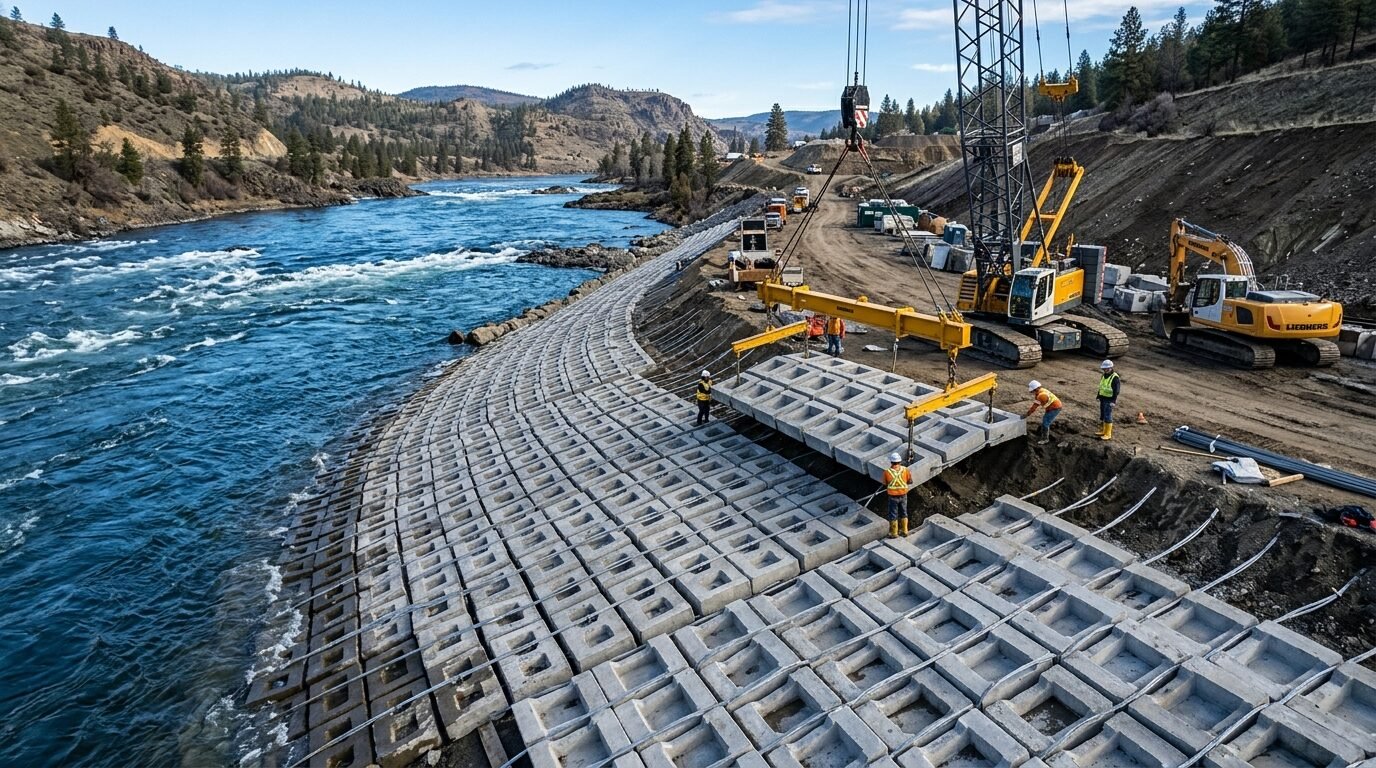
Roughly 60% of all bridge failures in the United States trace back to scour — the erosion of riverbed and bank material by flowing water. The FHWA has documented over 1,000 bridge failures attributed to scour since systematic records began, and those are just the cases with complete failure. Partial scour damage — undermined footings, cracked pile caps, differential settlement — is far more widespread and rarely makes national headlines.
The numbers get worse when you look globally. In China, flood-induced bridge collapses during major storm events kill hundreds of people per decade. In the UK, the Environment Agency has catalogued systematic scour vulnerability across thousands of highway bridges. The problem isn’t new knowledge — engineers have understood the hydraulic mechanics of scour for over a century. The challenge is that most scour occurs during peak flow events, when access is impossible and water turbidity makes underwater observation useless.
**What actually happens during a scour event**
When flow velocity increases around a bridge pier, the horseshoe vortex system at the base of the pier accelerates local bed shear stress by a factor of anywhere from 2.5 to 4.0 times the ambient bed shear. Natural river gravels and sands — even densely packed cohesive materials — can’t withstand that kind of sustained attack. The scour hole deepens progressively through the flood event, and in many cases the critical failure point arrives 12–24 hours after peak flow, when the scour hole has reached maximum depth but the structure hasn’t yet been inspected.
That lag between scour occurrence and discovery is one of the most dangerous characteristics of bridge failure — and it’s a central reason why pre-emptive armor protection is so strongly preferred over monitoring-only programs.
**The regulatory backdrop**
FHWA’s HEC-18 (*Evaluating Scour at Bridges*) and HEC-23 (*Bridge Scour and Stream Instability Countermeasures*) form the backbone of scour assessment and remediation practice in North America, and their influence extends internationally through adoption by transport ministries in Southeast Asia, the Middle East, and parts of Africa. Understanding these documents is non-negotiable for any engineer responsible for bridge scour risk.
Pier Scour vs Abutment Scour

Pier scour and abutment scour share the same root cause — flow acceleration around a structural obstruction — but they behave differently in terms of geometry, depth, and appropriate countermeasure design.
**Pier scour mechanics**
Pier scour is dominated by the horseshoe vortex that forms at the leading face of a pier and wraps around its perimeter. Scour hole geometry is roughly parabolic in cross-section, with maximum depth typically occurring 0.5–1.0 pier diameters upstream of the pier face. The equilibrium scour depth for a cylindrical pier in uniform sand can reach 2.0–2.4 times the pier diameter under design flood conditions — meaning a 2.0 m diameter pier could generate a scour hole 4.8 m deep at design flow.
Wake vortices on the downstream side extend the scour footprint significantly beyond the immediate pier perimeter. A complete pier scour protection layout must therefore extend at least 2.0–3.0 pier diameters radially from the pier centerline to cover both the horseshoe scour zone and the downstream wake zone.
**Abutment scour mechanics**
Abutment scour is driven by flow contraction. When flood flows overtop the floodplain and funnel through the bridge opening, the sudden velocity increase at the abutment face generates aggressive local scour. Abutment scour depths can exceed those of adjacent pier scour under spill-through conditions — values of 4.0–6.0 m are not uncommon for large floodplain bridges with moderate contraction ratios.
The geometry of abutment scour differs from pier scour in that it’s typically more laterally extensive and less symmetrical. Protection layouts need to cover the abutment face, the wingwall return, and the transition zone onto the natural bank slope — a challenge that armor systems with rigid or inflexible geometries struggle to address.
**Combination scour**
In practice, most bridge failures involve a combination of pier scour, abutment scour, and general contraction scour acting simultaneously during the same flood event. General scour lowers the entire riverbed at the bridge crossing, effectively pre-deepening the starting condition for pier and abutment scour. Engineers specifying countermeasures need to account for all three components in their design flood analysis.
Why ACM Is Preferred (HEC-23 Type 1 Scour Countermeasure)
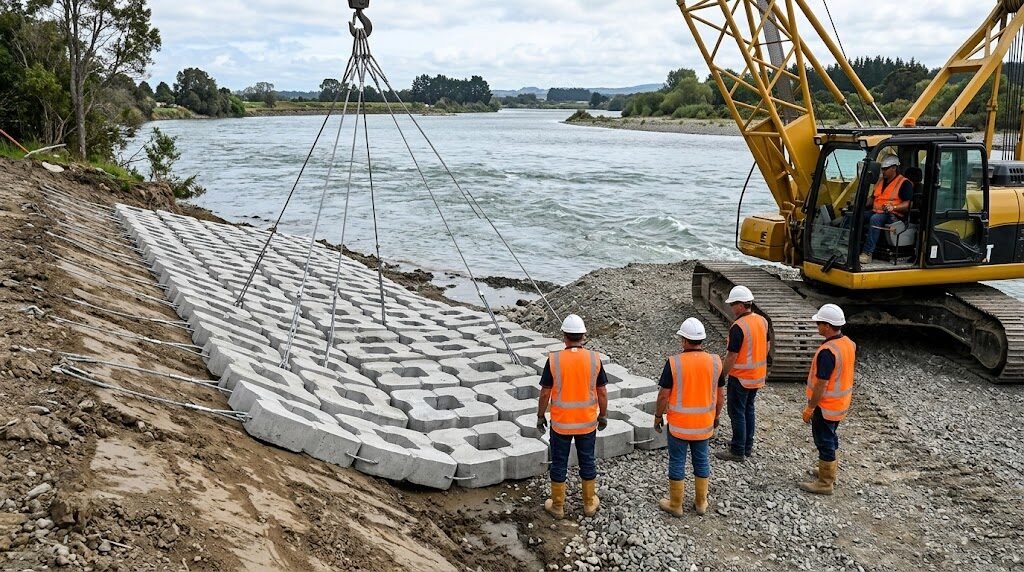
HEC-23 classifies scour countermeasures into two broad categories: Type 1 (armor countermeasures that protect the existing bed) and Type 2 (hydraulic countermeasures that modify flow patterns to reduce scour potential). Articulated concrete mattress is explicitly listed as a Type 1 countermeasure in HEC-23 and has earned that designation for well-documented engineering reasons.
**Conformability to scoured bed geometry**
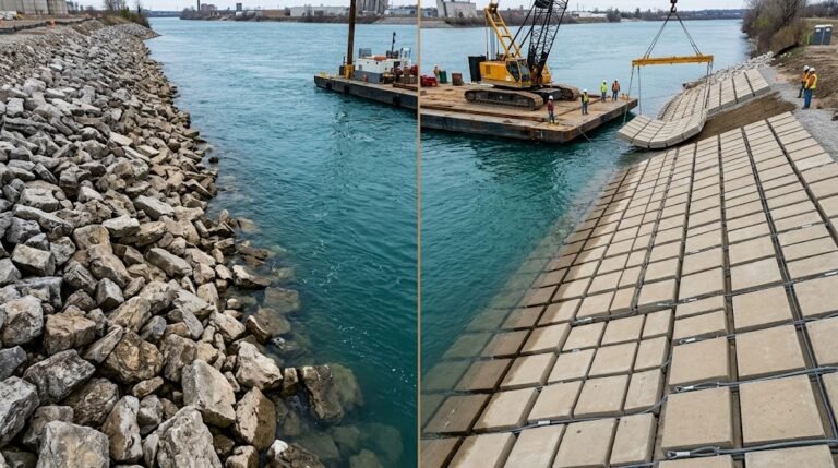
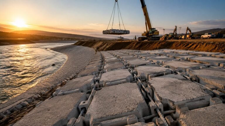
Unlike rigid concrete aprons, ACM consists of individual concrete blocks — typically 300×200×100 mm to 600×400×200 mm depending on velocity rating — connected by UV-stabilised HDPE cables or polypropylene ropes. This articulated structure allows the mattress to drape and conform to irregular or pre-existing scour hole geometry. When post-scour installation is required (which is common after an initial flood event has already excavated the bed), ACM follows the contour of the hole rather than bridging across it and creating an unsupported span that could collapse under live load.
**Resistance to displacement and undermining**
Riprap relies on the interlocking friction of individual stones to resist hydraulic lift and drag forces. ACM’s cable connection system means the individual blocks act collectively — a hydraulic uplift force acting on one block is distributed across adjacent blocks through the cable network, dramatically increasing the effective resistance to displacement. Block sizes and mattress weights are selected based on calculated bed shear stress using standard Manning-Strickler relationships, with typical mattress weights ranging from 50 kg/m² for low-velocity channel applications to 400 kg/m² for high-energy tidal or flood-exposed pier foundations.
Velocity ratings up to 6.0 m/s make properly specified ACM suitable for the extreme hydraulic conditions that develop around bridge piers during design flood events — conditions that frequently exceed the stability threshold of even well-graded riprap.
**Inspectability and post-event assessment**
Regulatory frameworks in most jurisdictions now require post-flood bridge scour inspections. ACM provides a recognisable, uniform surface that divers and sonar operators can assess clearly. Unlike riprap, which can shift subtly without obvious surface evidence, ACM displacement — cable breakage, block rotation, panel edge lifting — is visually identifiable during underwater inspection. That inspectability is a genuine operational advantage for highway authorities managing large bridge inventories.
**Geotextile filter compatibility**
ACM is installed directly over a geotextile filter layer, which prevents fine-grained bed material from piping through the armor and undermining the mattress from below. The geotextile specification (typically a non-woven needle-punched fabric with a filtration opening size matched to the local bed gradation) is an integral part of the countermeasure design — not an optional add-on. You can read more about the underlying scour protection mechanism in this guide to how articulated concrete mattresses protect riverbeds from scour.
**Comparison: ACM vs Riprap vs Grouted Rock**
| Parameter | ACM | Riprap | Grouted Rock |
|---|---|---|---|
| Max design velocity | 6.0 m/s | ~4.5 m/s (D50 = 0.5m) | 7.0+ m/s |
| Conformability to scour hole | Excellent | Moderate | Poor (rigid) |
| Post-event inspectability | High | Low | Moderate |
| Installation in flowing water | Possible (crane barge) | Difficult | Impractical |
| HEC-23 Type 1 designation | Yes | Yes | No |
| Flexibility for uneven substrate | High | Medium | None |
| Long-term settlement performance | Excellent | Variable | Poor (cracking risk) |
ACM Layout Design Around Bridge Piers
Layout design for pier scour protection isn’t just about covering a minimum area — it’s about understanding the full extent of the scour influence zone and sizing the protection accordingly.
**Horizontal extent**
HEC-23 guidance recommends that the armor protection extend a minimum of 2.0 times the pier width (or pier diameter for circular piers) from the pier face in all directions. For a rectangular pier 3.0 m wide and 10.0 m long, that translates to a protection zone extending 6.0 m from each long face and 6.0 m from each short face — a total plan area of roughly 22 m × 16 m = 352 m². Most experienced engineers add a 20–30% buffer to that minimum to account for uncertainty in design flood velocity estimates.
For abutment protection, the layout extends from the abutment face across the channel bed toward the pier, and transitions up the bank face at a slope typically not steeper than 1V:2H (50%). ACM slope protection design on embankments and levees uses similar principles — the mattress must be properly anchored at the crest and the toe to prevent progressive unraveling.
**Thickness and block selection**
Block thickness selection follows from the computed bed shear stress under design flood conditions. Using the Shields parameter approach:
- τ_c = θ_c × (γ_s − γ_w) × D
Where θ_c (critical Shields parameter) for ACM is typically taken as 0.04–0.06 based on product testing data, γ_s = 23.5 kN/m³ (concrete), and D is the effective block thickness.
For a design velocity of 3.5 m/s at the pier face (after applying the horseshoe vortex amplification factor of approximately 1.5–2.0 on ambient velocity), the required block thickness typically falls in the 150–200 mm range. At 5.0 m/s design velocity, you’re looking at 200–250 mm blocks as a minimum.
**Edge treatment**
The perimeter of the ACM apron is a critical zone. Hydraulic forces concentrate at the mattress edge, and an unsecured edge can progressively curl and unravel. Standard practice involves either burying the perimeter edge in a trench (minimum 0.5 m deep below predicted general scour elevation) or terminating against a concrete cutoff wall keyed into the foundation material.
**B2B Specification Checklist: Bridge Pier ACM Scour Protection**
| Design Parameter | Requirement | Notes |
|---|---|---|
| Design flood return period | 100-year minimum (500-year for critical bridges) | Check local transport authority requirements |
| Design velocity at pier face | Compute from HEC-RAS or 2D model | Apply vortex amplification factor 1.5–2.0× |
| Protection radius from pier centerline | Minimum 2.0 × pier width | Add 20–30% buffer |
| Block thickness | Per Shields parameter calculation | Typically 100–250 mm |
| Mattress weight | 50–400 kg/m² | Match to computed bed shear stress |
| Geotextile filter requirement | Non-woven, O90 matched to D85 of bed material | Mandatory — not optional |
| Edge termination | Buried trench or cutoff wall | Minimum 0.5 m below general scour elevation |
| Cable material | UV-stabilised HDPE or polypropylene rope | Inspect condition at each post-flood survey |
| Post-event inspection protocol | Diver survey or multibeam bathymetry | Within 72 hours of recession to normal stage |
Underwater Installation Considerations
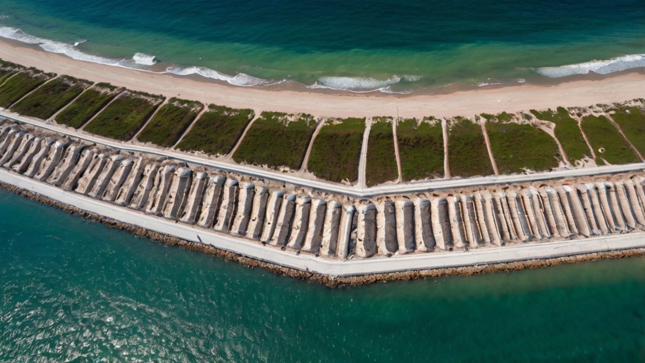
Installing ACM around an existing bridge pier in a live waterway is genuinely complex work — not something you can improvise on site with a general construction crew.
**Geotextile placement first**
The geotextile filter layer must be placed before the mattress. In shallow, low-velocity conditions this can be done by hand from a flat-bottomed barge, but in deeper water or at velocities above 0.5 m/s, the geotextile needs to be weighted or pinned to prevent it lifting and displacing before the ACM panels are placed over it. A loose or displaced geotextile is useless — or worse, it can bunch and create an irregular surface that prevents full mattress contact with the bed.
**Panel lifting and placement**
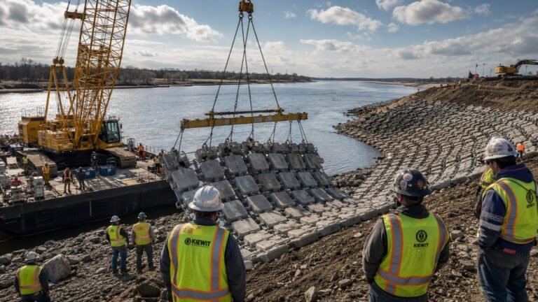
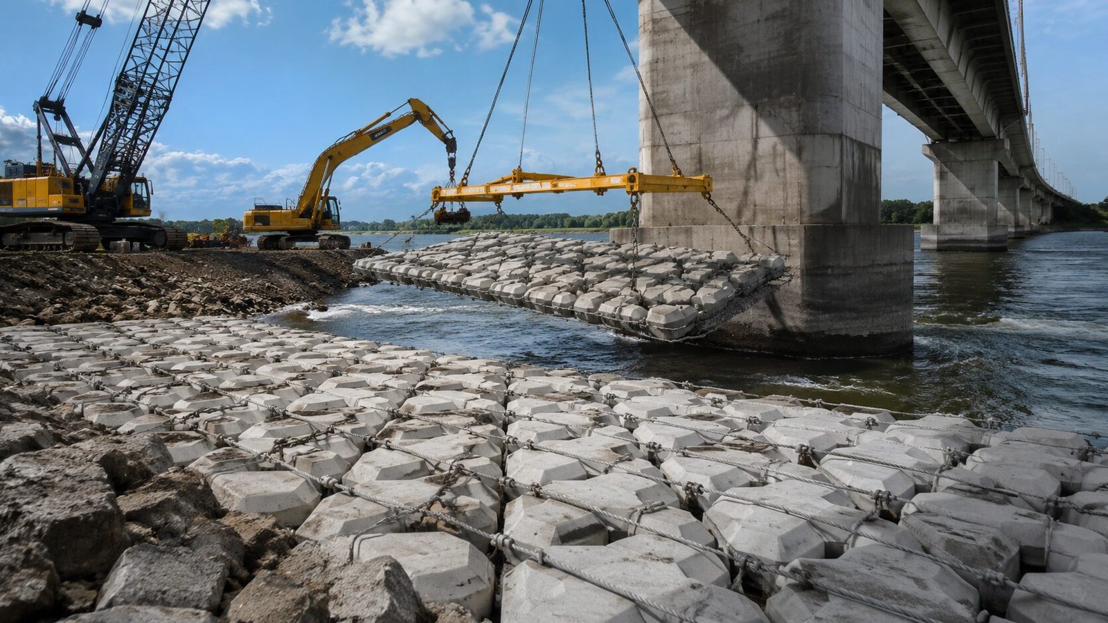
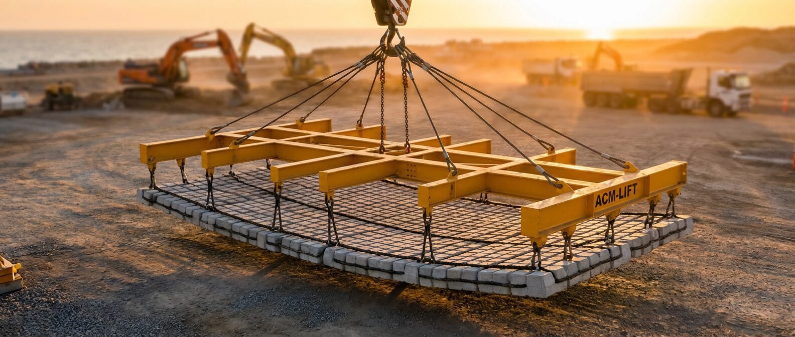
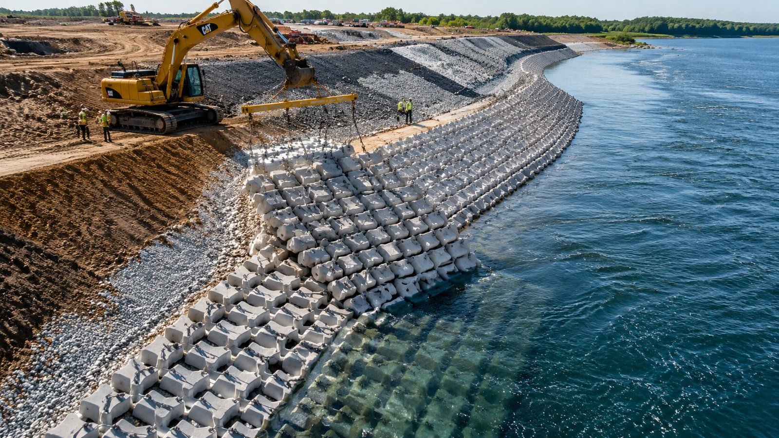
ACM panels are typically 3.0–6.0 m wide and 5.0–10.0 m long, weighing 2–25 tonnes per panel depending on block size and panel dimensions. Crane barge placement is the standard method for deep water or strong current conditions. The panel is suspended from a spreader beam, lowered through the water column, and positioned by divers using tag lines before the crane releases tension. Positioning accuracy in flowing water typically achieves ±0.3–0.5 m with experienced dive teams.
Proper use of ACM lifting frames for pier protection work significantly improves placement accuracy and reduces diver intervention time — which is the primary safety variable on underwater installation projects.
**Flow velocity constraints**
Practical underwater installation at flow velocities above 1.5–2.0 m/s becomes increasingly difficult and hazardous. Most specifications require installation to be staged during low-flow periods (typically dry season or flow-controlled periods below dam structures). Where this isn’t possible, temporary flow diversion or sluicing may be necessary.
**Panel overlap and jointing**
Adjacent ACM panels are overlapped by a minimum of 300–500 mm at their edges. Cable-tied systems can be connected panel-to-panel underwater by divers, creating a continuous armor surface with no unprotected gaps. Rope-tied systems typically rely on overlap alone. For high-velocity pier applications, cable-tied panel-to-panel connection is strongly preferred over rope-tied overlap.
Case References
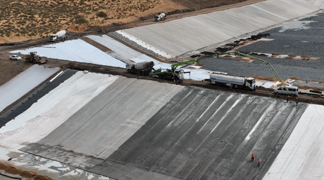
ACM pier and abutment scour protection has a documented performance record across diverse hydraulic environments.
In Southeast Asia, ACM has been deployed extensively at highway bridge crossings over braided river systems in the Mekong basin, where seasonal flow variations of 15:1 between dry and flood season create extreme scour demand. These installations typically use 200 mm block thickness at 280 kg/m² mattress weight, with panel-to-panel cable connection and perimeter burial trenches. Post-flood surveys conducted over multiple seasons have consistently shown stable mattress positions with no measurable displacement of panels correctly installed to design specification.
In tidal river environments — particularly estuarial bridge crossings where combined freshwater flood discharge and tidal reversal generate complex, multi-directional bed shear conditions — the conformability advantage of ACM over rigid apron solutions is especially pronounced. Tidal scour holes develop asymmetrically around piers, and a mattress that can drape and conform to that geometry outperforms a flat rigid apron that can only bridge across it.
For smaller bridge crossings at culvert outfalls, ACM also provides robust downstream scour protection. The principles of culvert outfall scour protection with articulated concrete mattress are directly transferable to smaller bridge structures where exit velocity control is the primary design driver.
Selecting the Right ACM Specification for Bridge Scour Protection
Once engineers have completed their scour assessment and confirmed ACM as the appropriate countermeasure, the specification process comes down to matching product parameters to the hydraulic demands of the specific site. That’s where working with a manufacturer who understands the engineering — not just the manufacturing — makes a practical difference.
Some manufacturers in the industry have invested in developing ACM product ranges that map directly to HEC-23 design parameters. HydroBase, for example, produces articulated concrete mattress panels across the full range of block sizes (300×200×100 mm through to 600×400×200 mm) with documented velocity ratings and DNV-GL certified cable systems — parameters that align directly with what project engineers need to complete their countermeasure design without substituting assumptions for tested data.
Their articulated concrete mattress product range covers both cable-tied and rope-tied configurations, open and closed block patterns, and panel sizes suited to both crane barge installation in major river crossings and manual installation at smaller bridge sites. For bridge scour applications specifically, the cable-tied configuration with panel-to-panel jointing capability is the appropriate selection — and having a manufacturer who can document pull-out force testing on cable terminations gives the design engineer the data needed to verify stability at design shear stress.
For engineers evaluating ACM against alternative countermeasures, this detailed comparison of ACM vs riprap vs gabions provides a structured framework for the selection decision.
Frequently Asked Questions
Q: How deep should ACM extend below the riverbed at a bridge pier?
ACM should extend to a depth at least 0.5 m below the predicted maximum scour elevation (combining pier scour, contraction scour, and general scour components per HEC-18). In practice, this means the perimeter burial trench or cutoff wall must be designed using the design flood scour depth calculation, not the existing bed elevation. Undersizing this depth is one of the most common and consequential errors in pier scour protection design.
Q: What is the maximum flow velocity ACM can withstand at bridge piers?
Properly specified ACM with 200–250 mm block thickness and cable-tied construction is rated to 6.0 m/s design velocity under sustained flow conditions. At bridge piers, the local velocity at the bed adjacent to the pier face is amplified by 1.5–2.0× above ambient channel velocity due to the horseshoe vortex — so the ACM block size must be selected against the amplified local velocity, not the approach flow velocity from the hydraulic model.
Q: What is the typical lead time and minimum order quantity for ACM for bridge scour projects?
Lead times for factory-produced ACM panels typically run 4–8 weeks from confirmed specification, depending on manufacturer capacity and panel size. Minimum order quantities vary by supplier but are generally project-based rather than panel-count based — most bridge scour projects require sufficient panel area to cover the full protection zone, which naturally meets production minimums. Contact manufacturers early in the design process to align production scheduling with construction programme requirements.
Q: How does ACM perform compared to riprap for bridge pier scour protection in cohesive bed materials?
ACM outperforms riprap in cohesive bed materials because it doesn’t rely on bedding into the substrate for stability.
Need a concrete mattress solution for your project?
HydroBase provides end-to-end concrete mattress engineering & installation services — from hydraulic design and factory-direct ACM supply to on-site supervision and post-project inspection. Trusted by civil engineers in 50+ countries.